

Introduction: Create Your Own Solar Powered Raspberry Pi Weather Station (Updated)


Note: This Instructable has been replaced with a new Grove based solder less instructable.
https://www.instructables.com/id/GroveWeatherPi-Ras...
In this Instructable you will learn:
- How to build a solar powered system
- How to design and size the panels and batteries
- How to gather data to analyze your system performance
- How to wire up a Raspberry Pi to a solar power system
- How to safely turn a Raspberry Pi on and off
- Building 3D Printed Parts for WeatherPi
And most importantly, have fun doing it!
This Instructable was updated on February 6, 2016 with new parts and wiring list.
What is WeatherPi?
WeatherPi is a solar powered Raspberry Pi WiFi connected weather station designed for Makers by SwitchDoc Labs. This is a great system to build and tinker with. All of it is modifiable and all source code is included. The most important functions are:
- Senses 20 different environmental values
- Completely Solar Powered
- Has a full database containing history of the environment (MySQL)
- Monitors and reports lots of data on the solar powered system - great for education!
- Self contained and monitored for brownouts and power issues
- Can be modified remotely
- Download your data to crunch it on your PC
- Can be modified to do SMS (Text) messaging, Twitters, webpages and more
- Has an iPad Based Control Panel
- Easy to connect to Twitter, WeatherUnderground, etc
This Instructable will show you how to build a WiFi Solar Powered Raspberry Pi Weather Station. This project grew out of a number of other projects, including the massive Project Curacao, a solar powered environmental monitoring system deployed on the Caribbean tropical island of Curacao. Project Curacao was written up in an extensive set of articles in MagPi magazine (starting in Issue 18 and continuing through Issue 22).
The WeatherPi Solar Powered Weather Station is an excellent education project. There are many aspects of this project that can be looked at and analyzed for educational purposes:
- How do solar power systems behave? Limitations and advantages
- Temperature, Wind and Humidity data analysis.
- Shutting down and starting up small computers on solar power
- Add your own sensors for UV, dust and pollen count and light color
Follow along on updates to the WeatherPi story on www.switchdoc.com.
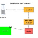
Step 1: The WeatherPi Block Diagram

The WeatherPi Block Diagram looks a lot more complicated than it actually is.
The first thing to notice that the dashed lines are individual boards (WeatherPiArduino and SunAirPlus) which contain a lot of the block diagram and the second thing is that all of the sensors to the left of the diagram plug into the WeatherPiArduino board which simplifies the wiring. Don't be intimidated!
The Subsystems
The Power Subsystem of WeatherPi uses a SunAirPlus Solar Power Controller which handles the solar panels, charging of the battery and then supplies the 5V to the Raspberry Pi and the rest of the system. It also contains sensors that will tell you the current and voltage produced by the Solar Panels and consumed by the batteries and the Raspberry Pi. Gather that Data! More Cowbell! It also contains the hardware watchdog timer and the USB PowerControl that actually shuts off the power to the Raspberry Pi during a brownout event (after the Pi shuts gracefully down under software control).
The Sensor Subsystem of WeatherPi uses a WeatherPiArduino as the base unit and then plugs in a bunch of optional sensors such as wind speed / direction / rain, lightning detect (how cool is that!), inside and outside temperature and humidity.
The Software Subsystem of WeatherPi runs in Python on the Raspberry Pi. It collects the data, stores in in a MySQL database, builds graphs and does housekeeping and power monitoring.
Step 2: WeatherPi Sensor Suite


The WeatherPi Sensor Suite senses the following environmental values:
- Wind Speed
- Wind Direction
- Rain
- Outside Temperature
- Outside Humidity
- Lightning Detection
- Barometric Pressure (and Altitude)
- Inside Box Temperature
- Inside Box Humidity
You can add more to the I2C bus and Analog to Digital Converter such as UV, dust counts, light color (sensing some types of pollution) and more! It's a great platform for expansion.
The sensor suite is built on the WeatherPiArduino board but there are several similar boards out there on the market.
Step 3: What's on the I2C Bus?

WeatherPi makes extensive use of the I2C bus on the Raspberry Pi.
At SwitchDoc Labs, we love data. And we love I2C devices. We like to gather the data using lots of I2C devices on our computers and projects. Project Curacao has a total of 12, WeatherPi has 11 devices and SunRover (a solar powered rover under development at SwitchDoc - you will see it as an Instructable in fall 2015) will have over 20 and will require one I2C bus just for controlling the motors. We are always running into conflicts with addressing on the I2C device. Since there are no standards, sometimes multiple devices will have the same address, such as 0x70 and you are just out of luck in running both of them on the same I2C bus without a lot of jimmy rigging.
To get around this addressing problem (and our conflict with an INA3221 and the Inside Humidity Sensor) we added an I2C Bus Multiplexer to the design which allows us to have many more I2C devices on the bus, irregardless of addressing conflicts. Here is our current list of I2C devices in WeatherPi:
| Device | I2C Address |
|---|---|
| BMP180 Barometric Pressure | 0x77 |
| Real Time Clock DS3231 | 0x68 |
| ATC EEPROM | 0x56 |
| ADS1015 Analog to Digital Converter | 0x49 |
| FRAM non-volatile storage | 0x50 |
| ADS1015 on SunAirPlus | 0x48 |
| INA3221 3 Channel Voltage/Current Monitor on SunAirPlus | 0x40 |
| HTU21D-F Humidity Sensor | 0x40 |
| Embedded Adventures Lightning Detector | 0x03 |
| AM2315 Outdoor Temp/Humidity | 0x5C |
| I2C 4 Channel I2C Bus Mux | 0x73 |
Here is what the I2C bus looks like on the Raspberry Pi. This is the output from the example code with the I2C 4 Channel Mux (hence there are 4 independent busses shown for the I2C bus).
Note that WeatherPi only uses Bus 0 and Bus 1.
Test SDL_Pi_TCA9545 Version 1.0 - SwitchDoc Labs

Sample uses 0x73
Program Started at:2015-05-10 20:00:56

-----------BUS 0-------------------
tca9545 control register B3-B0 = 0x1
ignore Interrupts if INT3' - INT0' not connected
tca9545 control register Interrupts = 0xc
     0  1  2  3  4  5  6  7  8  9  a  b  c  d  e  f
00:          03 -- -- -- -- -- -- -- -- -- -- -- --
10: -- -- -- -- -- -- -- -- -- -- -- -- -- -- -- --
20: -- -- -- -- -- -- -- -- -- -- -- -- -- -- -- --
30: -- -- -- -- -- -- -- -- -- -- -- -- -- -- -- --
40: 40 -- -- -- -- -- -- -- -- 49 -- -- -- -- -- --
50: 50 -- -- -- -- -- 56 -- -- -- -- -- -- -- -- --
60: -- -- -- -- -- -- -- -- 68 -- -- -- -- -- -- --
70: -- -- -- 73 -- -- -- 77

-----------------------------------

-----------BUS 1-------------------
tca9545 control register B3-B0 = 0x2
ignore Interrupts if INT3' - INT0' not connected
tca9545 control register Interrupts = 0xe
     0  1  2  3  4  5  6  7  8  9  a  b  c  d  e  f
00:          -- -- -- -- -- -- -- -- -- -- -- -- --
10: -- -- -- -- -- -- -- -- -- -- -- -- -- -- -- --
20: -- -- -- -- -- -- -- -- -- -- -- -- -- -- -- --
30: -- -- -- -- -- -- -- -- -- -- -- -- -- -- -- --
40: 40 -- -- -- -- -- -- -- 48 -- -- -- -- -- -- --
50: -- -- -- -- -- -- -- -- -- -- -- -- -- -- -- --
60: -- -- -- -- -- -- -- -- -- -- -- -- -- -- -- --
70: -- -- -- 73 -- -- -- --

-----------------------------------

-----------BUS 2-------------------
tca9545 control register B3-B0 = 0x4
ignore Interrupts if INT3' - INT0' not connected
tca9545 control register Interrupts = 0xc
     0  1  2  3  4  5  6  7  8  9  a  b  c  d  e  f
00:          -- -- -- -- -- -- -- -- -- -- -- -- --
10: -- -- -- -- -- -- -- -- -- -- -- -- -- -- -- --
20: -- -- -- -- -- -- -- -- -- -- -- -- -- -- -- --
30: -- -- -- -- -- -- -- -- -- -- -- -- -- -- -- --
40: -- -- -- -- -- -- -- -- -- -- -- -- -- -- -- --
50: -- -- -- -- -- -- -- -- -- -- -- -- -- -- -- --
60: -- -- -- -- -- -- -- -- -- -- -- -- -- -- -- --
70: -- -- -- 73 -- -- -- --

-----------------------------------

-----------BUS 3-------------------
tca9545 control register B3-B0 = 0x8
ignore Interrupts if INT3' - INT0' not connected
tca9545 control register Interrupts = 0xc
     0  1  2  3  4  5  6  7  8  9  a  b  c  d  e  f
00:          -- -- -- -- -- -- -- -- -- -- -- -- --
10: -- -- -- -- -- -- -- -- -- -- -- -- -- -- -- --
20: -- -- -- -- -- -- -- -- -- -- -- -- -- -- -- --
30: -- -- -- -- -- -- -- -- -- -- -- -- -- -- -- --
40: -- -- -- -- -- -- -- -- -- -- -- -- -- -- -- --
50: -- -- -- -- -- -- -- -- -- -- -- -- -- -- -- --
60: -- -- -- -- -- -- -- -- -- -- -- -- -- -- -- --
70: -- -- -- 73 -- -- -- --

-----------------------------------
<\pre>
Step 4: Sizing Your Solar Power System

One of the first things that comes up in a solar powered design is how to design the power system. The three main questions to be asked and answered are:
- How much power do I need?
- How many solar panels do I need?
- What size battery do I need?
The first thing you need to do when designing a solar powered system is to determine the power requirements for your solar powered design. Our criteria is that we want the WeatherPi Raspberry Pi Model A to run all day and at least three hours before sunrise and three hours after sunset. Our goals and budget influence our hardware choices, so they are not totally independent.
The table below contains estimated power consumption for models of the Raspberry Pi, including a Wireless USB dongle. We are assuming in each of these that you turn the HDMI port off which saves ~20ma.
| Model A | Model A+ | Model B | Model B+ | Model Pi2 B | |
|---|---|---|---|---|---|
| Current (mA) | 260(200) | 195(135) | 480(420) | 290(230) | 304(240) |
| Power (W) | 1.3 | 0.975 | 2.4 | 1.45 | 1.52 |
| Source | Measured | Measured | Measured | Measured | Measured |
All of the above measurements include about 60ma for the USB WiFi Dongle! Parenthetical numbers are without the 60ma.
Based on the above, first we will lay out my assumptions for our Raspberry Pi Model A+ based design. The LiPo batteries chosen will store 6600mAh. Why choose the Model A+? It's the lowest current consuming raspberry Pi!
What is mAh (milli Amp hours)? 6600mAh means you can take 100mA for 66 hours, theoretically. In actuality, you will not be able to get more than about 80% on average depending on your battery. How fast you discharge them also makes a big difference. Slower the discharge rate, the more mAh you can get out of the battery. For comparison, an AA battery will hold about 1000mAh[citation: http://en.wikipedia.org/wiki/AA_battery] and a D battery will hold about 10000mAh[citation: http://en.wikipedia.org/wiki/AA_battery]
In a system like this, it is best to charge your LiPo batteries completely and then hook up the computer and see how long it takes to discharge the battery and die. We did this test on the WeatherPi system. The results are here on switchdoc.com.
Assumptions:
- Two Voltaic 3.4W 6V/530ma Solar Cells (total of 6.8W) (530ma x 2 panels = 1060ma)
- 8 Hours of Sun running the cells at least at 70% of max Delivery of current to Raspberry Pi at 85% efficiency (you lose power in the charging and boosting circuitry)
- Raspberry Pi Model A+ takes 195mA on average (with the Wireless USB Dongle)
- Raspberry Pi Model A+ running 24 hours per day
- 6600mAh LiPo Batteries
Given these we can calculate total Raspberry Pi Model A runtime during a typical day:
PiRunTime = (8 Hours * 70% * 1060mA) *85% / (195mA) = 25 hours
Our goal was for 24 hours, so it looks like our system will work. 16 Hours of running the Raspberry Pi Model A+ on batteries alone will take (195mA/85%)*16 Hours = 3670mAh which is comfortably less than our 6600mAh batteries can store. The WIFI dongle added about 60mA on average. It was enabled the entire time the Raspberry Pi was on. No effort was made to minimize the power consumed by the WiFi dongle. Your results will depend on what other loads you are driving, such as other USB devices, GPIO loads, I2C devices, etc.
Note that during the day, on average, we are putting into the battery about 6000mAh.
This also means a bigger battery than 6600mAh will not make much difference to this system.
So, on a bright sunny day, we should be able to run 24 hours a day. Looking at the results from WeatherPi being out in the sun for a week, this seems to be correct. However, it will be cloudy and rainy and your system will run out of power. The next most important part of the design is how to handle Brownouts! See a step later in this Instructable about how to hand this nasty little problem.
The four most important parts of verifying your Solar Power Design:
- Gather real data
- Gather more real data
- Gather still more real data
- Look at your data and what it is telling you about the real system. Rinse and Repeat.
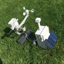
Step 5: The Power System


The power system in Weather Pi consists of four parts:
- Two Solar Panels
- One 6600Ah LiPo Battery
- SunAirPlus Solar Power Controller, Pi Power Supply and Data Gathering system
- USB PowerControl board for Pi Power Control
We are using 2 3.4W Solar Panels from Voltaic Systems. These are high quality panels that we have used in previous projects and last a long time even in the tropical sun. The picture above is of the same panels on Project Curacao after six months in the sun. Those are clouds reflected on the panels, not dirt. The panels are prefect.
We selected a 6600mAh battery from Adafruit for this design. See the "Sizing your Solar System" step below.
We are using a SunAirPlus Solar Power Controller in this design.
SunAirPlus includes an I2C INA3221 3 Channel Current / Voltage Monitor and a I2C 4 channel 12 bit Analog to Digital Converter (ADS1015). The INA3221 allows you to monitor all of the major currents and voltages in the system (Battery / Solar Panels / Load - Computer ). You can tell what your solar power project is doing in real time.
Here are some results from the SunAirPlus board using the onboard INA3221. You can see that the battery is almost fully charged and the solar cell voltage (actually a variable power supply on the test bench) is 5.19V and it is supplying 735mA.
Test SDL_Pi_INA3221 Version 1.0 - SwitchDoc Labs

Sample uses 0x40 and SunAirPlus board INA3221
Will work with the INA3221 SwitchDoc Labs Breakout Board


------------------------------
LIPO_Battery Bus Voltage: 4.15 V
LIPO_Battery Shunt Voltage: -9.12 mV
LIPO_Battery Load Voltage:  4.14 V
LIPO_Battery Current 1:  91.20 mA

Solar Cell Bus Voltage 2:  5.19 V
Solar Cell Shunt Voltage 2: -73.52 mV
Solar Cell Load Voltage 2:  5.12 V
Solar Cell Current 2:  735.20 mA

Output Bus Voltage 3:  4.88 V
Output Shunt Voltage 3: 48.68 mV
Output Load Voltage 3:  4.93 V
Output Current 3:  486.80 mA
You can use this board to power your projects and add a servo or stepper motor to allow it to track the sun using photoresistors to generate even more power.
The USB PowerController Board is basically a controlled Solid State Relay to turn the power on and off to the Raspberry Pi. This board sits between the Solar Power Controller (SunAirPlus) and a Raspberry Pi Model A+. The input to the board was designed to come directly from a LiPo battery so the computer won't be turned on until the LiPo battery was charged up above ~ 3.8V. A hysteresis circuit is provided so the board won't turn on and then turn immediately off because the power supply is yanked down when the computer turns on (putting a load not the battery). This really happens!!!! You kill Raspberry Pi SD Cards this way.
Step 6: Safely Turning the Pi on and Off


The Brownout Problem
In this important step, we are going to discuss the problem of powering down and up your Raspberry Pi. In Solar Powered systems, this is called the "Brownout Problem". We will be showing how to use a simple device, the USB Power Control from SwitchDoc Labs to solve this problem.
One of the most important issue in designing a Raspberry Pi Solar Power System is turning on and off. The "Brownout Problem" is a real issue. Why worry? If you have a long string of cloudy days, you may run your battery down. You can compensate for this in your design by adding more panels and more batteries, but that can get really expensive and your system might still run out of power, just a lot less frequently.
Shutting Off the Pi
Shutting a Raspberry Pi off is pretty easy. When the battery voltage falls below some value, you just do a “sudo shutdown -h now” and your Raspberry Pi will shutdown cleanly. After doing the test talked about here, we chose 3.5V as the voltage to shut down the Raspberry Pi.
Note that in most solar power systems, you need to monitor the battery voltage and not the 5V power supply because with most modern voltage booster systems, the circuitry will work very hard to keep the 5V going and then just give up crashing to a much lower voltage when it runs out of power.
That means your computer would have little or no warning when the voltage is about to drop. By monitoring the battery voltage, you can tell when the battery is getting low enough and then shut down your computer safely. For LiPo batteries, this will be when your voltage gets down to about 3.5V or so. This can all be monitored with the SunAirPlus solar charge controller that we are using in WeatherPi.
Starting the Pi
Enough about shutting down the computer. What about starting it up?
The Issue
You can’t just let the controller power up the computer. The problem is that the supply voltage will move up and down until there is enough charge in the battery to fully supply the computer. When the computer turns on (connecting a full load), you will pull the battery down hard enough to brown out the computer causing the Raspberry Pi to crash. This constant rebooting cycle can corrupt and ruin your SD card and cause your computer to never boot at all, even when the power is restored. We had this VERY thing happen to us 3500 miles away with Project Curacao. Arduinos are more tolerant of this, but Raspberry Pi’s do not like a ill-behaved power supply. You just can’t be sure of what state the computer will power up at without a good power supply.
This issue can be handled in a number of ways. The first is to use another computer (like an Arduino made to be very reliable by using a WatchDog - see the Reliable Computer series on switchdoc.com - http://www.switchdoc.com/2014/11/reliable-projects-watchdog-timers-raspberry-pi-arduinos/) to disconnect the Raspberry Pi’s power through a latching relay or MOSFET when there isn’t enough power. Project Curacao (http://www.switchdoc.com/project-curacao-introduction-part-1/) used this approach.
We didn't want to add an additional computer to WeatherPi, so we chose a second solution.
Power Your Pi Up and Down with the USB Power Control
A second (and cheaper!) way of handling the brownout and power up problem is to use a dedicated power controller that will shut the power off to the Raspberry Pi and restore the power when the battery voltage is high enough to avoid ratcheting the supply voltage up and down because of the load of the Raspberry Pi. This is called Hysteresis. We have designed a board to do just this (called the USB Power Controller) that will plug between the USB coming out of the SunAir Solar Power Controller and the Raspberry Pi as in the picture to the right.
The USB Power Controller Board
The USB PowerControl board is a USB to USB solid state relay.
Anything you can plug into a USB port can be controlled with USB PowerControl. It's easy to hook up. You connect a control line (a GPIO line or the output of a LiPo battery) to the LIPOBATIN line on the USB Power Control device and if the line is LOW (< ~3.3V) the USB Port is off. If it is HIGH (above 3.8V) the USB Port is turned on and you have 5V of power to the USB plug.
There is a hysteresis circuit so the board won't turn on and then turn immediately off because the power supply is yanked down when the computer turns on (putting a load not the battery).
There is little software for this device. You connect it directly to your LiPo battery for automatic control! The only software used detects the battery voltage and decides when to shut down the computer. The USB Power Control takes care of shutting the power to the Raspberry Pi when the battery voltage gets low enough. Note that a shutdown Raspberry Pi still draws current (according to one quick measurement, about 100ma).
One More Scenario
One last point. After thinking about the power down sequence, we came up with one more scenario. What if:
1) The battery voltage reaches 3.5V and the Raspberry Pi is shut down.
2) The USB PowerController will turn the power off when the battery reaches about ~3.4V.
However, what if the sun comes up at this time and the battery starts charging again? Then the USB PowerController will never reach ~3.4V and will never turn off. And the Pi will never reboot. Not a good scenario!
We fixed this by adding a hardware watchdog timer. For a tutorial on hardware watchdog timers, read the SwitchDoc series starting here.
We used a Dual WatchDog Timer Board to fix this problem. We set the RaspberryPi python to "pat the dog" (preventing the watchdog timer from triggering) every 10 seconds. The timer is set to trigger after about 200 seconds if it isn't patted. The timer is connected to pull the "COut" point down to ground on the USB PowerController which shuts off the Raspberry Pi. Because of the hysteresis circuit on the USB PowerController the Raspberry Pi will stay off until the battery voltage reaches ~3.9V and then the Pi will reboot. Now the above scenario will never happen. By the way, there is no real way of using the internal Pi Watchdog to do this. You don't want to reboot the Pi, you want to shut off the power in this scenario.
Step 7: The Parts List

No project is complete without a parts list. These are suggestions! There are lots of options for a number of these boards. If you substitute, make sure you check for compatibility!
Parts List (February 6, 2016)
- WeatherRack Weather Sensors
- BUD NEMA Box from Amazon.com
- VoltaicSystems Solar Panel(s) - 2 panels
- Raspberry Pi A+
- Raspberry Pi Compatible WiFi USB Dongle
- SunAirPlus Solar Power Controller
- USB Control (SwitchDoc Labs - now available)
- Grove 4 Channel I2C Mux Breakout Board w/Status LEDs
- SwitchDoc Labs Dual WatchDog Timer
- WeatherPiArduino Weather Board
- Embedded Adventures I2C Lightning Detector MOD-1016 board
- DS3231 RTC With EEPROM
- AM2315 Outdoor Temperature and Humidity Sensor
- BMP180 Barometer and Temperature Sensor
- Adafruit HTU21D-F Temperature/Humidity breakout board
- Adafruit 32KB FRAM I2C breakout board
- Adafruit ADS1015 4 Channel A/D I2C board
- Adafruit PKCELL Lithium Ion Battery Pack - 3.7V 6600mAh
- Waterproof 8 Pin Plug from Amazon.com
- 2 Dual Row 4 Position Covered Screw Terminal Block Strip from Amazon.com
- RasPiConnect Control Panel
Step 8: Building the Box


As with most projects, we tend to "breadboard" the circuitry before we put it into the enclosure. With WeatherPi, we spread out the parts, wired them up, made sure each of the major paths worked (and of course, took the obligatory nighttime geek shot) and then started placing them in the box, attaching them with screws and posts through the plastic.
Putting the WeatherPi into the BUD Industries box was pretty straight forward. We chose to put the solar power part of the circuit on top and the Raspberry Pi and the WeatherPiArduino Sensor array in the box bottom. The parts were all placed and then all the screw holes and outside screws were sealed with silicon caulking.
We used Gland Connectors to run the wires in and out of the box. Then we sealed the Gland Connectors. The Gland Connectors aren't necessarily waterproof, but they make things tighter and provide a good strain relief. We then used a waterproof disconnectable connector to tie into the WeatherRack weather instruments.
Step 9: 3D Printing and the WeatherPi


In building the WeatherPi Solar Powered Weather Station, we saw a couple of parts that we decided it would be good to 3D Print. In the 6 months since we bought our SwitchDoc Labs MakerBot Replicator, we have totally changed the way we build special parts for prototyping. And with the latest extruder and firmware updates, the MakerBot rocks! I have done 10 long prints with no problem. It used to be Xacto knives and foam, wood and glue, but now we just build new parts when we need them. The three parts we have used 3D Printing for so far are:
- Bracket with Hinges to connect solar panel panels to weather station box (adjustable for latitude)
- Opposite hinge on which to hang solar power panels (the tabs on the side of the rectangle are just to make sure the bracket is flat!)
- Sun Cover for AM2315 Temperature and Humidity Sensor - we killed the Humidity sensor in one of these in the sun in Project Curacao.
Here are the OpenSCAD files.
Step 10: The Raspberry Pi Python Software

A big part of the WeatherPi project is the software. All of the python software for this project is up on github at the switchdoclabs section. We also included all of the various libraries for the I2C devices we are using.
Non-Normal Requirements for your Pi
You will need to add the following software and libraries to your Raspberry Pi
MySQL
There are lots of tutorials on the net for installing MySQL. Here is the one we used.
Addition on July 22, 2015: The structure of the WeatherPi MySQL database in mysqldump format is located on github https://github.com/switchdoclabs/WeatherPiSQL. You can use this file to build the MySQL database for the WeatherPi Project.
MatPlotLib
This is the graphing subsystem with a great interface to Python. It is a bit more complex to install, so we wrote a tutorial on how to install it on SwitchDoc.com. Note that the installation takes a long time, about 8 hours on a Raspberry Pi (mostly unattended).
The WeatherPi Python Software
The WeatherPi software is pretty simple. The application was much less complex than the Project Curacao software so we decided not use the apscheduler package and decided just to use a simple loop with a "every 15 seconds" type of control. Here is the main loop:
secondCount = 1
while True:

        # process Interrupts from Lightning

        if (as3935Interrupt == True):
                process_as3935_interrupt()


        # process commands from RasPiConnect
        print "---------------------------------------- "

        processCommand()

        if ((secondCount % 10) == 0):
                # print every 10 seconds
                sampleAndDisplay()
                patTheDog()      # reset the WatchDog Timer
                blinkSunAirLED2X(2)


        # every 5 minutes, push data to mysql and check for shutdown


        if ((secondCount % (5*60)) == 0):
                # print every 300 seconds
                sampleWeather()
                sampleSunAirPlus()
                writeWeatherRecord()
                writePowerRecord()

                if (batteryVoltage < 3.5):
                        print "--->>>>Time to Shutdown<<<<---"
                        shutdownPi("low voltage shutdown")


        # every 15 minutes, build new graphs

        if ((secondCount % (15*60)) == 0):
                # print every 900 seconds
                sampleAndDisplay()


        # every 48 hours, reboot
        if ((secondCount % (60*60*48)) == 0):
                # reboot every 48() hours seconds
                rebootPi("48 hour reboot")


        secondCount = secondCount + 1
        # reset secondCount to prevent overflow forever

        if (secondCount == 1000001):
                secondCount = 1

        time.sleep(1.0)
Note that we reboot the Pi every two days. Why do we do that? We have noticed that after heavy usage of MatPlotLib and/or MySQL, that sometimes after a long time, you run out of resources, giving all sorts of odd behavior. Since the RaspberryPi A+ has a small amount of RAM, rebooting is the easiest way of fixing it.
Check out all the code up on github.com.
The code for the RasPiConnect control panel is discussed in another step.
Step 11: Building a Control Panel Using RasPiConnect

We use RasPiConnect to build our control panels for our projects. It allows us to put graphs, controls, buttons, sliders, etc. up on our iPad/iPhone screens without having to write apps. RasPiConnect works on Raspberry Pi's and on Arduinos. We have used this software on 5 different projects, with WeatherPi being the latest.
How to build a control panel for WeatherPi is beyond the scope of this Instructable, but here is the tutorial we wrote for doing what we are doing for WeatherPi. We are using the same command passing mechanism in WeatherPi that we used in MouseAir. RasPiConnect comes with an excellent, comprehensive manual here.
All the RasPiConnect code that we used in WeatherPi is on github under github.com/switchdoclabs. Note that only the directory local is uploaded as that is the only places changes to the code are made as explained in the RasPiConnect manual.
Step 12: Full Wiring List

Following is the complete wiring list for WeatherPi. As you wire it, check off each wire for accuracy.
Key:
Raspberry Pi A+:PiA+
Grove I2C Bus Mux: GI2CM
Dual WatchDog Timer Board:WDT
WeatherPiArduino:WPA
USB Power Control: USBPC
SunAirPlus: SAP
| Raspberry Pi A+ (PiA+) | ||
|---|---|---|
| GPIO Header | ||
| From | To | Description |
| PiA+ GPIO/Pin 1: 3.3V | GI2CM JP1/Pin 3:VCC | Power for I2C Mux Board - Computer Interface |
| PiA+ GPIO/Pin 2: 5.0V | WDT JP1/Pin 1:VDD | Power for Dual WatchDog Timer Board |
| PiA+ GPIO/Pin 3: SDA | GI2CM JP1/Pin2:SDA | SDA for I2C Mux Board - Computer Interface |
| PiA+ GPIO/Pin 5: SCL | GI2CM JP1/Pin1:SCL | SCL for I2C Mux Board - Computer Interface |
| PiA+ GPIO/Pin 6: GND | GI2CM JP1/Pin4:GND | GND for I2C Mux Board - Computer Interface |
| PiA+ GPIO/Pin 11 GPIO 17 | WDT JP2/Pin1:DOG1_TRIGGER | Trigger Input for WatchDog 1 Timer (Pat the Dog) |
| PiA+ GPIO/Pin 12: GPIO 18 | WPA JP13/Pin1: LD-IRQ | Interrupt Request from the AS3935 on Lightning Detector Board |
| PiA+ GPIO/Pin 16: GPIO 23 | WPA JP2/Pin3:Anemometer | Anemometer Output from WeatherRack - Interrupt |
| PiA+ GPIO/Pin 17: 3.3V | VCC Screw Connector | To provide more 3.3V Connections |
| PiA+ GPIO/Pin 18: GPIO 24 | WPA JP2/Pin 2:Rain Bucket | Rain Bucket Output from WeatherRack - Interrupt |
| PiA+ GPIO/Pin 22: GPIO 25 | SAP JP13/Pin8: EXTGP0 | GP0 on SunAir Board - Yellow LED display |
| Grove I2C Mux Board (GI2CM) | ||
|---|---|---|
| JP1 - Computer | ||
| GI2CM JP1/Pin 2:SDA | PiA+ GPIO/Pin 3:SDA | SDA to I2C Mux Board - Computer Interface |
| GI2CM JP1/Pin 1: SCL | PiA+ GPIO/Pin 5:SDA | SCL to I2C Mux Board - Computer Interface |
| GI2CM JP1/Pin 4: GND | PiA+ GPIO/Pin 6:GND | GND for I2C Mux Board - Computer Interface |
| GI2CM JP1/Pin 3: VCC | PiA+ GPIO/Pin 1: 3.3V | Power for I2C Mux Board - Computer Interface |
| JP2 - I2C Bus 0 | WeatherPiArduino I2C Bus | |
| GI2CM JP2/Pin 3: VDU0 | WPA JP1/Pin 2: VDD | 3.3V from WPA Board |
| GI2CM JP2/Pin 2: GND | WPA JP1/Pin 1: GND | GND for WPA Board |
| GI2CM JP2/Pin 5: SC0 | WPA JP4/Pin 1: SCL | SCL for WPA Board |
| GI2CM JP2/Pin 4: SD0 | WPA JP4/Pin 2: SDA | SDA for WPA Board |
| JP3 - I2C Bus 1 | SunAirPlus I2C Bus | |
| GI2CM JP3/Pin 3: VDU1 | SPA JP23/Pin 3: VDD | 5.0V for Bus 1 for I2C Mux |
| GI2CM JP3/Pin 2: GND | SAP JP13/Pin 4: GND | GND for SAP Board |
| GI2CM JP3/Pin 5: SC1 | SAP JP13/Pin 1: EXTSCL | SCL for SAP Board |
| GI2CM JP3/Pin 4: SD1 | SAP JP13/Pin 2: EXTSDA | SDA for SAP Board |
| JP4 - I2C Bus 3 | Auxiliary GND for WDT Board | |
| GI2CM JP4/Pin2: GND | WDT JP1/Pin 1:GND | GND for WDT Board |
Dual WatchDog Timer Board (WDT) | ||
|---|---|---|
| JP1 | ||
| WDT JP1/Pin 1: VDD | PiA+ GPIO/Pin 2:VDD (5.0V) | |
| WDT JP1/Pin 2: GND | GI2CM JP4/Pin 2:GND | GND for WDT Board |
| JP2 | ||
| WDT JP2/Pin 1: DOG1_TRIGGER | PiA+ GPIO/Pin 11:GPIO 17 | WDT Trigger from Raspberry Pi |
| JP3 | ||
| WDT JP3/Pin 1: DOG1_ARDUINORESET | USBPC: TP3 - COUT | Solder Wire to TP3 - COUT on USB PowerControl |
| WeatherPiArduino (WPA) | |||
|---|---|---|---|
| JP1 | |||
| WPA JP1/Pin 1: GND | GI2CMux JP2/Pin 2: GND | GND for WPA Board from GI2CMux | |
| WPA JP1/Pin 2: 3V3 | GI2CMux JP2/Pin 3: VDU0 | 3.3V for I2C Bus 0 from WPA | |
| JP2 | |||
| WPA JP2/Pin 2: Rain Bucket | PiA+ GPIO/Pin 18: GPIO 24 | Rain Bucket Output from WeatherRack - Interrupt | |
| WPA JP2/Pin 3: Anemometer | PiA+ GPIO/Pin 16: GPIO 23 | Anemometer Output from WeatherRack - Interrupt | |
| JP4 | |||
| WPA JP4/Pin 1: SCL | GI2CMux JP4/Pin 5: SCL | SCL from GI2C Mux Board | |
| WPA JP4/Pin 2: SDA | GI2CMux JP4/Pin 4: SDA | SDA from GI2C Mux Board | |
| WPA JP4/Pin 3: 3V3 | VCC Screw Connector | 3.3V From Pi/Screw Connector | |
| JP13 | |||
| WPA JP13/Pin 1: LD-IRQ | PiA+ GPIO/Pin 12: GPIO 18 | Interrupt Request from the AS3935 on Lightning Detector Board |
| USB Power Control (USBPC) | ||
|---|---|---|
| USBIN: USB Connector from SAP | USB A OUT on SAP | |
| USBOUT: USB Connector to PiA+ | USB Power Input on PiA+ | |
| JP1 | ||
| USBOUT JP1/Pin 1: LIPOBATIN | SAP JP4/Pin1: LiPo Battery Out | SAP Plus of LiPo Battery Out to USB PowerControl |
| TP3 - COUT: | WDT JP3/Pin 1: DOG1_ARDUINORESET | Shuts USB Power Control down if Raspberry Pi has been shutdown and LIPOBATIN < ~3.9V |
| SunAirPlus (SAP) | ||
|---|---|---|
| USB A Out: | USBIN on USBPC | |
| J5 Battery: | To LiPo Battery Pack | |
| J6 Solar: | To Solar Panels | |
| JP4 | ||
| SAP JP4/Pin 1: | USBPC: JP1/Pin1 LIPOBATIN | SAP Plus of LiPo Battery Out to USB PowerControl |
| JP10 | ||
| SAP JP10/Pin 1: SCL | SCL (5.0V) | Connected to Outdoor Temp/Hum AM2315 Sensor - works better on 5.0V I2C Bus |
| SAP JP10/Pin 2: SDA | SDA (5.0V) | Connected to Outdoor Temp/Hum AM2315 Sensor - works better on 5.0V I2C Bus |
| SAP JP10/Pin 3: VDD5 | VDD5 | Connected to Outdoor Temp/Hum AM2315 Sensor - works better on 5.0V I2C Bus |
| SAP JP10/Pin 4: GND | GND | Connected to Outdoor Temp/Hum AM2315 Sensor - works better on 5.0V I2C Bus |
| JP13 | ||
| SAP JP13/Pin 1: EXTSCL | GI2CMux JP3/Pin 5: SC1 | SCL |
| SAP JP13/Pin 2: EXTSDA | GI2CMux JP3/Pin 4: SD1 | SD |
| SAP JP13/Pin 3: VDD | SPA JP23/Pin2: VDD5 | 5V I2C Interface from SAP |
| SAP JP13/Pin 4: GND | GI2CMux JP3/Pin 2: GND | GND form GI2CMux Board |
| SAP JP13/Pin 8: EXTGP0 | PiA+ GPIO/Pin 22: GPIO 25 | Line from Raspberry Pi to flash SAP Yellow LED on GP0 |
| JP23 | ||
| SAP JP23/Pin 2: VDD5 | SAP JP13/Pin 3: VDD | 5.0V for SAP I2C Bus to GI2CMux |
| SAP JP23/Pin 3: VDD5 | GI2CMux JP3/Pin 3: VDU1 | 5.0V for IG2CMux I2C Bus1 |
Step 13: Obsolete Parts List (as of February 6th, 2016) for Weather Pi
On February 6, 2016, the I2C Mux board was replaced with the new model Grove I2C Mux with Status LEDs.
------------------
This parts list is presented for completeness.
-------------------
No project is complete without a parts list. These are suggestions! There are lots of options for a number of these boards. If you substitute, make sure you check for compatibility!
Parts List (Obsolete as of February 6, 2016)
- WeatherRack Weather Sensors
- BUD NEMA Box from Amazon.com
- VoltaicSystems Solar Panel(s) - 2 panels
- Raspberry Pi A+
- Raspberry Pi Compatible WiFi USB Dongle
- SunAirPlus Solar Power Controller
- USB Control (SwitchDoc Labs - now available)
- 4 Channel I2C Mux Breakout Board
- SwitchDoc Labs Dual WatchDog Timer
- WeatherPiArduino Weather Board
- Embedded Adventures I2C Lightning Detector MOD-1016 board
- DS3231 RTC With EEPROM
- AM2315 Outdoor Temperature and Humidity Sensor
- BMP180 Barometer and Temperature Sensor
- Adafruit HTU21D-F Temperature/Humidity breakout board
- Adafruit 32KB FRAM I2C breakout board
- Adafruit ADS1015 4 Channel A/D I2C board
- Adafruit PKCELL Lithium Ion Battery Pack - 3.7V 6600mAh
- Waterproof 8 Pin Plug from Amazon.com
- 2 Dual Row 4 Position Covered Screw Terminal Block Strip from Amazon.com
- RasPiConnect Control Panel
Step 14: Obsolete Wiring List (as of February 6, 2016)
OBSOLETE as of February 6, 2016
Following is the complete wiring list for WeatherPi. As you wire it, check off each wire for accuracy.
Key:
Raspberry Pi A+:PiA+
I2C Bus Mux: I2CM
Dual WatchDog Timer Board:WDT
WeatherPiArduino:WPA
USB Power Control: USBPC
SunAirPlus: SAP
| Raspberry Pi A+ (PiA+) | ||
|---|---|---|
| GPIO Header | ||
| From | To | Description |
| PiA+ GPIO/Pin 1: 3.3V | I2CM JP1/Pin 4:VCC | Power for I2C Mux Board - Computer Interface |
| PiA+ GPIO/Pin 2: 5.0V | WDT JP1/Pin 1:VDD | Power for Dual WatchDog Timer Board |
| PiA+ GPIO/Pin 3: SDA | I2CM JP1/Pin1:SDA | SDA for I2C Mux Board - Computer Interface |
| PiA+ GPIO/Pin 5: SCL | I2CM JP1/Pin2:SCL | SCL for I2C Mux Board - Computer Interface |
| PiA+ GPIO/Pin 6: GND | I2CM JP1/Pin3:GND | GND for I2C Mux Board - Computer Interface |
| PiA+ GPIO/Pin 11 GPIO 17 | WDT JP2/Pin1:DOG1_TRIGGER | Trigger Input for WatchDog 1 Timer (Pat the Dog) |
| PiA+ GPIO/Pin 12: GPIO 18 | WPA JP13/Pin1: LD-IRQ | Interrupt Request from the AS3935 on Lightning Detector Board |
| PiA+ GPIO/Pin 16: GPIO 23 | WPA JP2/Pin3:Anemometer | Anemometer Output from WeatherRack - Interrupt |
| PiA+ GPIO/Pin 17: 3.3V | VCC Screw Connector | To provide more 3.3V Connections |
| PiA+ GPIO/Pin 18: GPIO 24 | WPA JP2/Pin 2:Rain Bucket | Rain Bucket Output from WeatherRack - Interrupt |
| PiA+ GPIO/Pin 22: GPIO 25 | SAP JP13/Pin8: EXTGP0 | GP0 on SunAir Board - Yellow LED display |
| I2C Mux Board (I2CM) | ||
|---|---|---|
| JP1 - Computer | ||
| I2CM JP1/Pin 1:SDA | PiA+ GPIO/Pin 3:SDA | SDA to I2C Mux Board - Computer Interface |
| I2CM JP1/Pin 2: SCL | PiA+ GPIO/Pin 5:SDA | SCL to I2C Mux Board - Computer Interface |
| I2CM JP1/Pin 3: GND | PiA+ GPIO/Pin 6:GND | GND for I2C Mux Board - Computer Interface |
| I2CM JP1/Pin 4: VCC | PiA+ GPIO/Pin 1: 3.3V | Power for I2C Mux Board - Computer Interface |
| I2CM JP1/Pin 5: RESET’ | VCC Screw Connector | 3.3V From Pi/Screw Connector |
| JP2 - I2C Bus 0 | WeatherPiArduino I2C Bus | |
| I2CM JP2/Pin 2: VD0 | WPA JP1/Pin 2: VDD | 3.3V from WPA Board |
| I2CM JP2/Pin 3: GND | WPA JP1/Pin 1: GND | GND for WPA Board |
| I2CM JP2/Pin 4: SC0 | WPA JP4/Pin 1: SCL | SCL for WPA Board |
| I2CM JP2/Pin 5: SD0 | WPA JP4/Pin 2: SDA | SDA for WPA Board |
| JP3 - I2C Bus 1 | SunAirPlus I2C Bus | |
| I2CM JP3/Pin 2: VD1 | SPA JP23/Pin 3: VDD | 5.0V for Bus 1 for I2C Mux |
| I2CM JP3/Pin 3: GND | SAP JP13/Pin 4: GND | GND for SAP Board |
| I2CM JP3/Pin 4: SC1 | SAP JP13/Pin 1: EXTSCL | SCL for SAP Board |
| I2CM JP3/Pin 5: SD1 | SAP JP13/Pin 2: EXTSDA | SDA for SAP Board |
| JP4 - I2C Bus 3 | Auxiliary GND for WDT Board | GND for WDT Board |
| I2CM JP4/Pin 3: GND | WDT JP1/Pin 1:GND | GND for WDT Board |
Dual WatchDog Timer Board (WDT) | ||
|---|---|---|
| JP1 | ||
| WDT JP1/Pin 1: VDD | PiA+ GPIO/Pin 2:VDD (5.0V) | |
| WDT JP1/Pin 2: GND | I2CM JP4/Pin 3:GND | GND for WDT Board |
| JP2 | ||
| WDT JP2/Pin 1: DOG1_TRIGGER | PiA+ GPIO/Pin 11:GPIO 17 | WDT Trigger from Raspberry Pi |
| JP3 | ||
| WDT JP3/Pin 1: DOG1_ARDUINORESET | USBPC: TP3 - COUT | Solder Wire to TP3 - COUT on USB PowerControl |
| WeatherPiArduino (WPA) | |||
|---|---|---|---|
| JP1 | |||
| WPA JP1/Pin 1: GND | I2CMux JP2/Pin 3: GND | GND for WPA Board from I2CMux | |
| WPA JP1/Pin 2: 3V3 | I2CMux JP2/Pin 2: VD0 | 3.3V for I2C Bus 0 from WPA | |
| JP2 | |||
| WPA JP2/Pin 2: Rain Bucket | PiA+ GPIO/Pin 18: GPIO 24 | Rain Bucket Output from WeatherRack - Interrupt | |
| WPA JP2/Pin 3: Anemometer | PiA+ GPIO/Pin 16: GPIO 23 | Anemometer Output from WeatherRack - Interrupt | |
| JP4 | |||
| WPA JP4/Pin 1: SCL | I2CM JP2/Pin 1: SCL | SCL from I2C Mux Board | |
| WPA JP4/Pin 2: SDA | I2CM JP2/Pin 2: SDA | SDA from I2C Mux Board | |
| WPA JP4/Pin 3: 3V3 | VCC Screw Connector | 3.3V From Pi/Screw Connector | |
| JP13 | |||
| WPA JP13/Pin 1: LD-IRQ | PiA+ GPIO/Pin 12: GPIO 18 | Interrupt Request from the AS3935 on Lightning Detector Board |
| USB Power Control (USBPC) | ||
|---|---|---|
| USBIN: USB Connector from SAP | USB A OUT on SAP | |
| USBOUT: USB Connector to PiA+ | USB Power Input on PiA+ | |
| JP1 | ||
| USBOUT JP1/Pin 1: LIPOBATIN | SAP JP4/Pin1: LiPo Battery Out | SAP Plus of LiPo Battery Out to USB PowerControl |
| TP3 - COUT: | WDT JP3/Pin 1: DOG1_ARDUINORESET | Shuts USB Power Control down if Raspberry Pi has been shutdown and LIPOBATIN < ~3.9V |
| SunAirPlus (SAP) | ||
|---|---|---|
| USB A Out: | USBIN on USBPC | |
| J5 Battery: | To LiPo Battery Pack | |
| J6 Solar: | To Solar Panels | |
| JP4 | ||
| SAP JP4/Pin 1: | USBPC: JP1/Pin1 LIPOBATIN | SAP Plus of LiPo Battery Out to USB PowerControl |
| JP10 | ||
| SAP JP10/Pin 1: SCL | SCL (5.0V) | Connected to Outdoor Temp/Hum AM2315 Sensor - works better on 5.0V I2C Bus |
| SAP JP10/Pin 2: SDA | SDA (5.0V) | Connected to Outdoor Temp/Hum AM2315 Sensor - works better on 5.0V I2C Bus |
| SAP JP10/Pin 3: VDD5 | VDD5 | Connected to Outdoor Temp/Hum AM2315 Sensor - works better on 5.0V I2C Bus |
| SAP JP10/Pin 4: GND | GND | Connected to Outdoor Temp/Hum AM2315 Sensor - works better on 5.0V I2C Bus |
| JP13 | ||
| SAP JP13/Pin 1: EXTSCL | I2CMux JP3/Pin 4: SC1 | |
| SAP JP13/Pin 2: EXTSDA | I2CMux JP3/Pin 5: SD1 | |
| SAP JP13/Pin 3: VDD | SPA JP23/Pin2: VDD5 | 5V I2C Interface from SAP |
| SAP JP13/Pin 4: GND | I2CMux JP3/Pin 3: GND | GND form I2CMux Board |
| SAP JP13/Pin 8: EXTGP0 | PiA+ GPIO/Pin 22: GPIO 25 | Line from Raspberry Pi to flash SAP Yellow LED on GP0 |
| JP23 | ||
| SAP JP23/Pin 2: VDD5 | SAP JP13/Pin 3: VDD | 5.0V for SAP I2C Bus to I2CMux |
| SAP JP23/Pin 3: VDD5 | I2CM JP3/Pin 2: VD1 | 5.0V for I2CMux I2C Bus1 |
Step 15: Results!


The WeatherPi has been outside for about 2 weeks now. Working perfectly. You can see the box being charged up and then going to battery power as the sun moves behind the house. We have had hot days and cold nights as we are just starting to move out of Spring into Summer. It is not quite generating enough electricity to run 24 hours at the moment (because it is in the shade until 9am and after about 3pm - not quite 8 hours of sun). This will be fixed when we move it up to the top of the house where it will have sun about 12 hours a day on average (when the sun is not behind clouds!).
What is Left To Do (as of May 10, 2015)?
We have the following issues to address:
We are working three small issues.
1) The plug for the WeatherRack Weather Sensors need to be better secured to the outside of the box. Right now it is just attached and sealed by silicon caulking. Too easily broken with small amounts of pressure. We have Gland Connector pressure cable pass throughs that we can use for this.
2) The cheap RT5370 Wireless Adapter WiFi dongle we are using is shutting itself down occasionally. The Raspberry Pi keeps running, collecting data, etc., but we are locked out of the system. When we look at the WiFi adaptor when it has shut itself down, it is no longer blinking blue, but the Raspberry Pi and all the external hardware is still running. Looking at the web shows some people having had similar problems with this dongle. We have now replaced it with a WiPi USB Dongle which works well. Interestingly enough, the WiPi USB dongle reports it is using the RT5370 also, but the WiPi works.
3) Humidity is too high inside of the box. We are going to add small vent hole at the bottom of the box to correct for this. Don't want that condensing humidity.
Improvements
We aren't building graphs for the Wind Speed, Direction and Rain yet. Just reporting the current values on the RasPiConnect control panel. All the data is being saved into MySQL, however.
The temperature and lightning displays need to be fixed and improved.
The cool thing is that all of this can be done remotely!
Step 16: What Else Can You Do With This?

Here are some additional ideas for projects based on WeatherPi:
- Replacing the WiFi with a GSM data connection (or just send text messages)
- Make it tweet the weather!
- Make a custom Facebook posting with your weather
- Adding a GPS receiver and store that data. You now have a mobile weather station! When it gets back to WiFi all the stored data will be available.
- Adding additional air quality sensors, UV sensors, Dust sensors. You have a lot of I2C addressing space that you can fill
- Connect to the WeatherUnderground or similar services
Step 17: Conclusion


WeatherPi is a flexible WiFi connect solar powered Weather Station architecture. It is designed to be a reliable data gathering system that can be placed outdoors in a remote location for an extended amount of time. It is not designed for extreme environments such as extremely cold locations, but it will work in most places for an extended period of time.
Tinker with the design! Change it! Modify it! Let us know what you are doing with WeatherPi!

Participated in the
Mind for Design

Participated in the
Backyard Contest

Participated in the
Coded Creations


