

Introduction: Create Your Own Amazing Disco Bar!


Using MIT's controller boards used for their Disco Dance Floor, I've created a computer controlled Disco Bar using 128 RGB LED's, 250' of cable, and a built in fridge! Learn how to make your own and impress your friends!
Or if you just can't wait, watch the final video of my bar in action on YouTube:
http://youtube.com/watch?v=jkqoPkuJaMI
Step 1: Introduction
I wanted to keep this document focused on the hardware and software aspect of the bar, so I will not be talking about any of the woodwork. It is up to you to come up with your own unique idea!
I will be going over the following topics:
- What equipment I used
- Model #'s of all the parts and components I used
- How I soldered MIT's controller boards
- How to put the firmware onto the Atmega8L chip
- How I made the cables, and what connectors I used
- Installing the cables into your design.
- How to use Clint's controller software.
- How I made the animations
The first step is to buy MIT's controller boards! You can purchase them here:
http://www.dropoutdesign.com/products/ddf.html
You have three options when ordering your boards:
1. Buy an unpopulated board and purchase the components yourself.
2. Buy a kit which includes a bare board and all necessary parts.
3. Buy a premade board. Expensive, but saves you a ton of soldering.
Step 2: Equipment


These are the tools that you will need to complete this project.
Step 3: Bill of Materials
This is my bill of materials.
NOTE: Anything you DON'T see listed here is the same as MIT's bill of materials. What I have listed here are the custom parts I ordered that are specific to my design or that were not listed on MIT's bill of materials. You can see MIT's bill of materials listed in their latest documentation, which you can get below.
It goes:
Part
Model #
Where I ordered it
Red resistor pack
742C083221JCT-ND
Digikey.com
Blue resistor pack
742C083820JCT-ND
Digikey.com
Green resistor pack
742C083680JCT-ND
Digikey.com
Switch resistor pack
742C083102JCT-ND
Digikey.com
RGB LED's
RL5-RGB (common anode)
Superbrightleds.com
Headers for boards
WM4003-ND
Digikey.com
Metal crimps for cables
538-08-50-0005
Mouser.com
Housing for cables
10-11-2053
Jameco.com
SIPP connectors
102200
Jameco.com
Ribbon Cable
37760
Jameco.com
AVR Programmer
ATSTK500-ND
Digikey
Attachments

Step 4: How I Soldered MIT's Controller Boards


NOTE: I am writing this documentation based on revision 1.17 of the controller boards. There is a newer 2.05 version out as of right now. The procedure is pretty much identical, but double check MIT's documentation as well if you have the newer boards. (You can get their documentation on the previous step) First off, you want to make sure you have the smallest, sharpest tip on your soldering iron. Some of the components are ridiculously small, and if you are using an old dull tip, you will have a very hard time.
1. The first items I soldered on were the resistor packs. MIT recommends doing the LED drivers first, but this is the way I did it. First, put a little solder flux on every pad where the resistors will be seated. Second, using your tweezers, place the resistor pack right onto the pads. The flux is kind of sticky, so it should hold it in place. Next, press directly down on the resistor pack so it doesn't move at all, and press the tip of your soldering iron right where the board and component meet. You only need to do this on one or two of the pins just to tack it in place. Now that it is held in place with a couple of joints, go around, and very carefully add a tiny bit of solder to each joint.
2. Next, I soldered on the LED Drivers. You basically follow the same procedure as the resistor packs. I actually found these to be easier to solder than the resistor packs. Solder flux, tack down a couple joints, put some solder on every joint. That's it!
3. Now that the resistor packs and LED drivers are on, its time for the rest of the small components. This includes the capacitors that you see as well as all the chips and resistors located at the bottom of the board. You should have the hang of it by now after doing 16 LED drivers and 64 resistor packs.
If you have not noticed yet, we are starting with all the lowest components. If you solder on all the high stuff first, it is very hard to get a soldering iron in there to solder stuff.
The next step is to solder the higher components. This includes the ISP connector, USB connector, Power connector, and diagnostic LED's. These are thru-hole components, and are very easy to solder. Just be sure you have the LED's in the correct orientation, or they will not light up.
4. Now its time for the cable headers. For my design, I went with a basic .1' male square header. You can find the model number in my BOM. Solder on all 64 of them. I found that if you tape a whole row down, then flip the board over, you can solder a whole row of 16 real quick.
5. At this point, you should be done soldering the boards. We hope! What you need to do now is put the board up to a bright light, and using a magnifying glass, look at each and every joint and pad to make sure that you have no shorts and to make sure everything is connected correctly. You can also use desoldering braid to get rid of any bridges you may have.
Step 5: Put the Firmware on the Atmega8L Chip


The Final step of the boards is to put the firmware on the Atmega8L chip. For this, I used the STK-500. You can use the less expensive AVR-ISP to do this step as well. The programmer connects to your computer through the serial port, and then you connect it to the controller board with a short cable to the ISP connector.
You will need to get AVR Studio to complete this step. You can get their latest build at: http://www.atmel.com/dyn/resources/prod_documents/aStudio4b460.exe
1. Verify you can talk to the board. Do this by clicking the READ button on the Advanced screen.
2. Check your fuse settings.
3. Set your lock bits.
4. Under Flash where it says "Input HEX file" use the firmware attached at the bottom of this step.
5. Click program and then verify to be sure it programmed properly.
Attachments

Step 6: Making the Cables


I have made a mini cable that I will be using to show you how I put it all together. I bought a 20 connector ribbon cable, and then ripped it into strands of 4. If you are going to be using the sensors, you will need to rip them in strips of 5. I am not using the sensors, so I am only using 4. On one end of the cable, it has a header that plugs into the controller boards, and on the other end, it has the LED. I'll be showing you the various parts I used to create the cable. You can find the part numbers listed in my BOM.
1. Separate and strip each strand of the cable. Strip off about 0.25' of the casing. Solder on the metal pins.
2. Insert the metal pins into the housing. You should have no metal exposed when they are all the way in.
3. For the LED end, I soldered a SIPP connector to the wires. However, you can't solder them in order. The controller boards are oriented VSBGR and the LED's are VRBG. To see how to wire it, take a look at the pictures.
4. For the SIPP connectors, the pin side is what is soldered to the cable. The other side has holes where you can "plug in" the LED. Make sure the polarity of the LED is correct. I also used heat shrink tubing, because the braided ribbon cable can get a little messy, and it keeps it neat.
All of my cables range between 3' and 1' depending on how far away they are from the controller boards. My initial decision was to just use the same length for every cable, but I scratched that idea because I had SO MUCH extra cable. It's better to measure the length for each cable.
5. Then, the final step is to indicate which side is +5V so it's easy to connect to the controller boards. I colored the +5 side with a blue permanent marker.
Step 7: Installing the Cables Into Your Design


You could be making any number of designs, whether it be a bar, floor, on a wall, etc... But now is the time to install the cables into your design!
For my design, I mounted the boards on the inside sidewall of the cabinet. I then ran cable underneath the top through a hole in each cell, and over to the controller boards. I would have liked to run the cables in-between the cells, but I did not have enough room to do that. Here are some various pictures of how I ran the cable, what the LED's look like inside the cells, and how I connected the power supply to the controller boards:
NOTE: Before you get carried away and install all the cables, you need to mark where the cable is with regard to your setup. With 128 cables, it gets very hard to figure out which cable is which. If you look at one of the pictures below, you'll notice numbers written on every cable. This helped me when it came time to plug the cables into the controller boards. I knew exactly where every cable should go.
Step 8: Connect the Controller Boards to Your Computer

The first thing you do is power up the boards, and plug them into your computer with a USB cable. Your computer should find a new device and ask you for drivers. You need to install the VCP (Virtual COM Port) drivers from http://www.ftdichip.com/Drivers/VCP.htm If everything is working correctly at this point, you should see something similar in your device manager.
NOTE: I have 2 boards connected, which is why I have two entries. If you have 8 boards for example, you should have 8 entries after you go through all the driver setup stuff. Keep track of the COM ports for the next step!!
Step 9: Using Clint's Controller Software


Now that the boards are connected to your computer, the next step is to download the controller software. I will be showing you Clint Rutkas' Controller Software designed for Windows. You can download his software at:
http://www.betterthaneveryone.com
I will be showing you version 0.0.4.0
The only configuring you have to do is with your config file.
Change the animation directory to wherever you stored the animations. At this point, you should download MIT's animations if you haven't done so already
get them here: http://web.mit.edu/storborg/ddf/sw/disco-anim.tar.gz
Then, change the TilesPerRow, and RowsPerModule to work with your setup. With my setup, I have two boards with 8x8 layouts, which when laid side by side give me my final layout of 16x8. This can change depending on how you want to set it up. For example, MIT's setup is a 16x4 layout with 8 of them side by side giving them a final layout of 32x16.
The last step is to enter in the ComPorts. I have an entry for each of my boards. You remembered which COM ports, right? If you have 8 boards, you will need to enter in all 8. The tricky part is putting them in the correct order. If you do not put them in the correct order, the animations will not show up correctly.
NOTE: If you want to just play around with the program and not actually send animations to your design, you can change DisableComPortWrite to true so that it does not write to the boards.
There's also a picture of what the Mock Floor looks like. It shows you what is playing on your design in real time.
Step 10: Make Your Own Animations!

To make your own animations, you will need MATLAB. I know they sell a $100 version somewhere. Otherwise, go pay a poor college student to let you use an engineering computer lab at a college campus. They for sure have it installed :-)
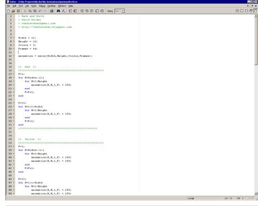
To create your own animation, basically what you do is create a 4-D array in MATLAB with (row, column, color, frame) Then you start coding your design with whatever you want. The next step is to use MIT's conversion file to convert the 4-d array into a file that is readable by the controller boards.
You can see a screenshot of me executing the backandforth animation, and then converting it into backandforth.ddf, which is the final animation file.
All the numbers listed are it going through each frame. There are 64 frames in this animation.
NOTE: I still design my animations for a 32x16 layout so that they work with the other Dance Floor designs. Clint's program is able to resize them down to 16x8, so I am able to do this.
I've attached MIT's conversion file, my backandforth.m MATLAB file, and my final backandforth.ddf file for you to play around with.
In case you were wondering, the backandforth animation is the last one that plays in my video, which you can see in the last step!
Step 11: Conclusion
So, hopefully you've decided to build yourself an amazing Disco design! Here are some links to more pictures and movies of my bar!
High resolution pictures:
http://www.davidworden.com/thediscobar.zip
Some older pictures during the building process:
http://thediscobar.blogspot.com/2005/12/pictures.html
My final video on YouTube:
http://youtube.com/watch?v=jkqoPkuJaMI
My final video on Google Video:
http://video.google.com/videoplay?docid=1186173102912721570
My Disco Bar blog:
http://thediscobar.blogspot.com


