

Introduction: Custom Arduino Shield and Sensors


Overview:
This instructable will construct a series of custom sensor modules and an Arduino shield. Such modules are available from many different sources, but fans of the Instructables website would probably find satisfaction in making their own. Each module will be a set size of 1.5cm by 2.5cm and employ a three pin connector of the form Signal-Voltage-Ground. The custom shield will break out the Arduino pins into the same Signal-Voltage-Ground configuration. Thus, electronic connections will be reduced to using a three pin cable to attach a sensor to its corresponding pin set on the Arduino shield. Uniformly spaced mounting holes at the corners of the modules will allow for interchangeable configurations on a robot deck or in other electronics projects. The embedded video displays the sensors in action on an autonomous obstacle avoiding robot. The Arduino code for the robot is given below. The light sensors described in step three of this instructable were also used in my previous instructable.
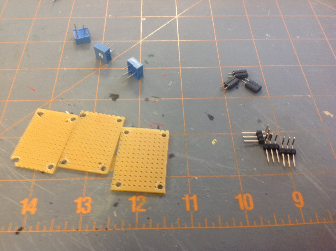
The construction of the sensors will involve some basic materials including several perf boards, header strips, socket strips and three pin cables. Both straight and right angle headers will be used. The perf boards need to be cut into several 1.5cm by 2.5cm rectangles with a screw hole drilled into each corner. (See figures in the following steps.) In the following steps, an image note in the upper left will give each figure a number of the form Figure x-x. For example, Figure 2-4 refers to the fourth figure of step two.
Step 1: Leaf Switches


Components:
2x 10K resistors
2x three pin connectors
2x sensor platforms
suitable nuts and bolts
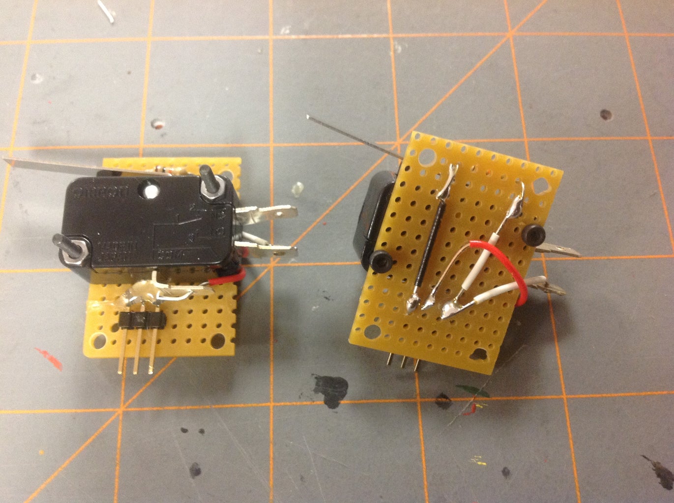
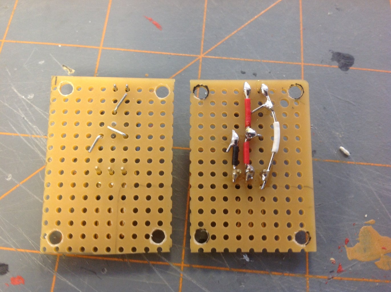
The leaf switches are designed to be used as contact sensors on the sides of a robot. Thus they will be constructed as mirror image pairs, one for the left side and one for the right side of the robot. Placement of the components for the left leaf switch are shown on the left in Figure 1-2. I hot glued the three pin connector into place, but I used nuts and bolts to secure the switch itself to the sensor platform for greater stability. Solder a white wire from normally open contact on the switch to the signal pin of the sensor. See figure 1-3. (Note, for all of the sensors in this instructable, when the three pin connector is positioned on the sensor platform and pointing down, the pin order from left to right is Signal, Voltage, Ground. Of course when viewing the back side of the sensor, the order from left to right is Ground, Voltage, Signal.) Next, solder a white wire from the signal pin to one lead of the 10K resistor. Solder a black wire from other end of the 10K resistor to the ground pin. Finally, solder a red wire from the common contact of the switch to the voltage pin. The resistor pulls the signal pin low. Pressing the switch then pulls the signal pin high.
Step 2: Buttons


Components:
2x buttons
2x 10K resistors
2x three pin connectors
2x sensor platforms
Hot glue the components into place as shown on the left of Figure 2-2. On the back side of the sensor, bend the resistor leads toward the outer pins of the three pin connector and solder. Solder a white wire from the signal pin to one side of the switch. Solder a red wire from the voltage pin to the other side of the switch. Don't forget to solder all four switch leads for stability. (I originally only soldered the two leads connected to the wires and the button began to rock back and forth.)
Step 3: Light Sensors


Components:
3x 250K potentiometers
3x two pin sockets
3x three pin connectors
3x sensor platforms
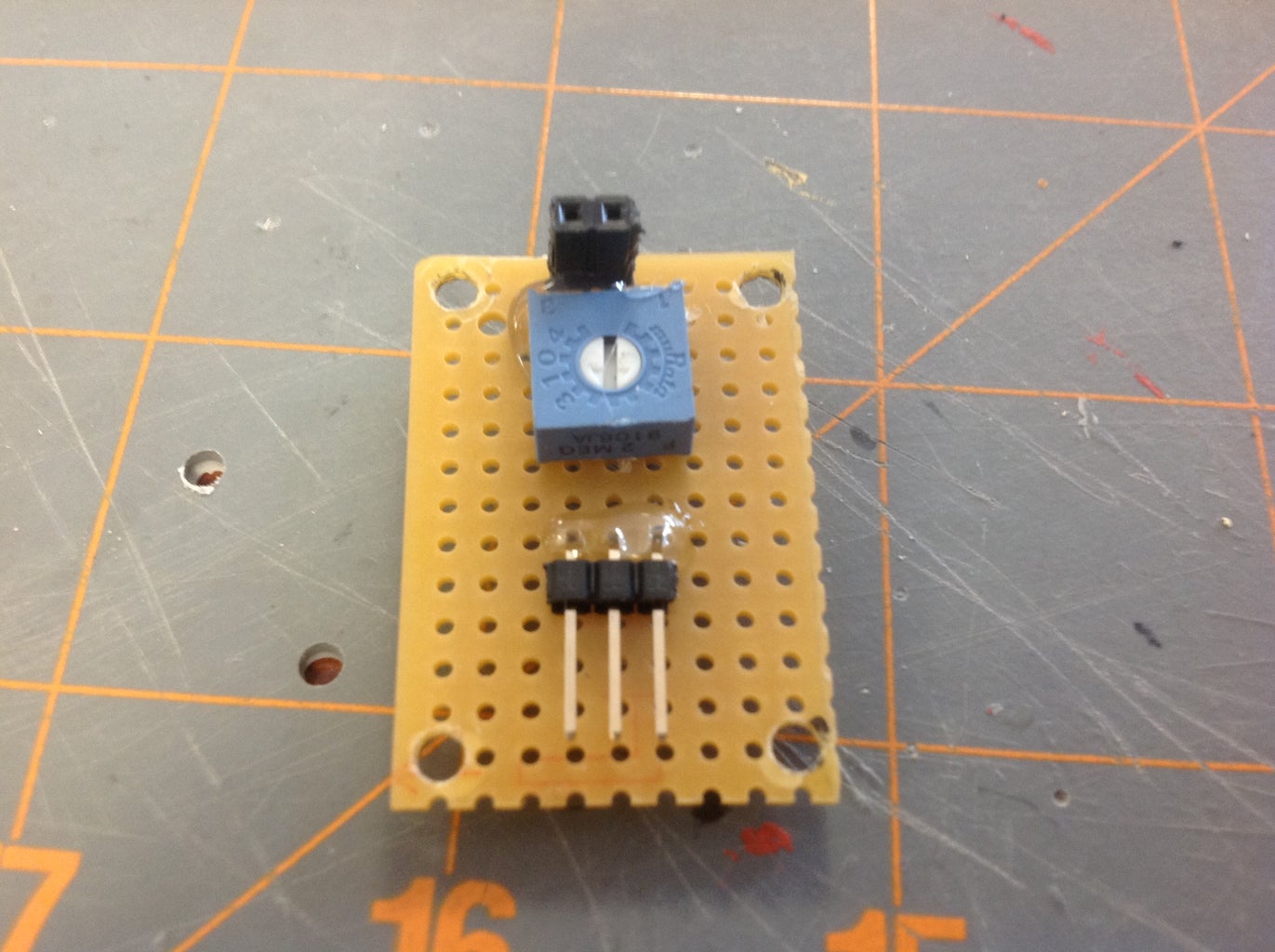
The directions given here will closely mirror those of my previous instructable. Each light sensor will consist of a voltage divider made from a photoresistor and a 250K potentiometer. First, hot glue the components into place as shown in Figure 3-2. Bend the leads of the potentiometer as show in Figure 3-4. Take a white wire and solder the right most connector pin (as viewed from the back) to the potentiometer wiper and right socket lead. Use a red wire to solder the left socket lead to the right potentiometer lead and the center connector pin. Use a black wire to solder the remaining potentiometer lead to the remaining connector pin. Next, place some shrink tubing around the legs of the photoresistors before inserting them into the sockets. See Figure 3-5. This gives the sensor a nice finished look and of course also prevents shorts. (I picked up this shrink tube tip from BIGDOG1971's light following robot instructable.) These voltage dividers can also be used with other sensors such as flex sensors and force sensors.
Step 4: IR Distance Sensor


Components:
1x sensor platorm
For this module I simply hot glued the IR sensor to the sensor platform.
Step 5: Ultrasonic Distance Sensor


Components:
1x four pin cable
1x sensor platform
Again, this module consists of the the sensor hot glued to the sensor platform. You may want to use a small piece of wood or cardboard under the "eyes" of the sensor since it does not quite fit on the platform. Also, the HC-SR04 sensor that I used does not conform to the three pin configuration of the other sensors. This requires a dedicated four pin node on the Arduino shield as described in Step 10.
Step 6: Buzzer


Components:
1x buzzer
1x three pin connector
1x sensor platform
Hot glue the components into place as shown in Figure 6-2. Take a white wire and solder the positive lead of the buzzer to the signal pin and use a black wire to solder the negative lead of the buzzer to the ground pin. The voltage pin is left unconnected.
Step 7: Laser


Components:
1x three pin connector
1x sensor platform
Gently disassemble the laser pointer and remove the laser component. Be sure to identify the positive and negative contacts for the laser. Hot glue the laser and three pin connector to the sensor board as shown in Figure 7-2. On the laser that I used, the negative contact was the spring that went to the negative side of the laser pointer batteries. The positive lead was where the laser pointer button made contact with the laser unit. Solder the negative laser lead to the ground pin with a black wire and solder the positive laser lead to the signal pin with a white wire.
Step 8: LEDs


Components:
2x LEDs
2x two pin sockets
2x three pin connectors
2x sensor platforms
Hot glue the components into place as shown on the left of Figure 8-2. Bend the potentiometer leads as shown on the left of Figure 8-3. Use a white wire to solder the signal pin to the wiper of the potentiometer. As viewed from the back, solder the right socket lead to the closest potentiometer lead. Use a black wire to solder the left socket lead to the ground pin. I used a 1K potentiometer because I figured this could be adjusted to the proper resistance for any common LED. As viewed from the front, the signal socket will be on the left and the ground socket on the right. Thus, insert the longer end of the LED into the left socket and the shorter end into the right socket. See Figure 8-4. To measure the resistance, take out the LED and connect one end of an ohmmeter to a piece of wire and insert it into the left socket (as viewed from the front). Connect the other end of the ohmmeter to the signal pin. Adjust the protentiometer to the value needed for your LED.
Step 9: Arduino Shield


Components:
1x Arduino protoshield PC board
20x three pin connectors
1x four pin connectors
2x six pin connectors
2x eight pin connectors
2x two pin sockets
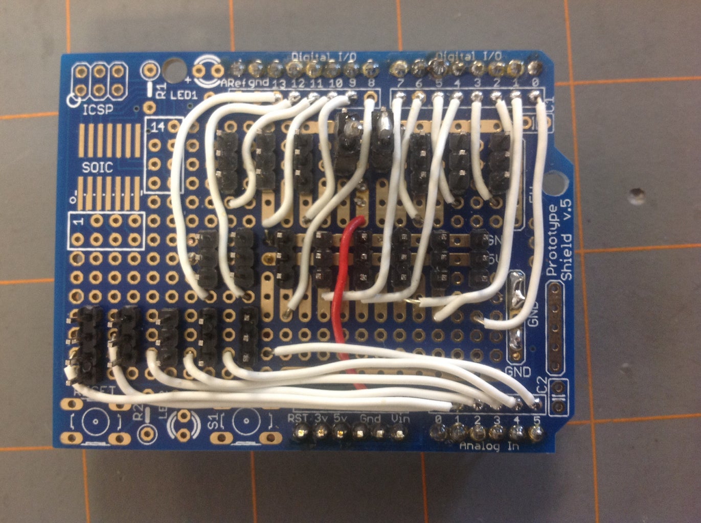
Constructing the Arduino shield was the most challenging part of the project. The finished product can be seen from the front and the back in Figures 9-2 and 9-3. To get a clearer idea about the wiring, refer to Figures 9-5, 9-6 and 9-7. In those figures, the black rectangles denote the positions of 20 three pin connectors and the 1 four pin connector. (Recall, the ultrasonic sensor of step 5 required a four pin connection.) The first thing I did was solder the connectors to the bare Arduino board. Don't use flush cutters to cut off the connector leads on the back side of the board as the leads are too thick and will probably damage the flush cutters. I used heavy duty tin snips to cut those leads.
The first wire connections I made were those depicted in Figure 9-5. The white lines are wires connecting the Arduino pins to the signal pin of the appropriate three pin connector. These connections appear as the white wires in Figure 9-2. The YELLOW lines in Figure 9-5 are the continuation of the white wires UNDER the shield to the designated pin. I would strip bare an extra inch of wire, poke it through the indicated hole in Figure 9-5, and then on the underside of the shield I would bend the bare wire around the signal pin and solder. This is the YELLOW connection in Figure 9-5. The red line in Figure 9-5 takes the input battery voltage (Vin) and connects it to the two pins indicated by the YELLOW connections. (Again, those connections are on the underside of the shield.)
Figure 9-6 shows the connections on the underside of the shield. A note of explanation is needed here. The digital PWM pins on the Arduino (D3, D5, D6, D9, D10 and D11) are often used to drive servos, including continuous rotation servos used as wheels on a robot. Thus, they sometimes draw a lot of current. Thus, it would be nice if they could be driven from input batteries directly and not the regulated 5V from the Arduino. At the top of Figure 9-6, two black rectangles extend higher than the others. The top pins of those rectangles lie on the Arduino 5V rail. The bottom pins of those rectangles are connected to the input battery voltage by the red line in Figure 9-5. The middle pin of one of those rectangles connects to the voltage pins of D3, D5 and D6. The middle pin of the other rectangle connects to the voltage pins of D9, D10 and D11. Thus, on the topside of the Arduino board, a jumper can be used to connect the PWM pins to the 5V rail if they are connected to low current sensors, or to the input battery voltage if the PWM pins are connected to high current wheel servos. (More on this later.)
Back to the connections in Figure 9-6. The black lines connect the ground pins to the Arduino ground rail. The red line at the bottom of Figure 9-6 connects the voltage pins of the analog connectors to 5V. The red line in the middle of Figure 9-6 connects the voltage pins of the non-PWM digital connectors to the 5V rail. The upper red lines in Figure 9-6 connect the voltage pins of the PWM digital connectors to one of the two jumper controlled connectors described in the last paragraph. The pins are rather close, which meant I had to use a lot of bare wire as can be seen in Figure 9-3. Luckily I didn't end up with any shorts. Finally, the six pin and eight pin connectors are inserted through the bottom of the shield and soldered on to provide the connectors for the shield to an Arduino.
To make the jumpers for the PWM pins I just took a pair of two pin sockets and soldered the pins together. These can bee seen on the left in Figure 9-4. Figure 9-7 shows the labels for the shield. Sensors can now be connected by the three pin cables to any one of the black rectangles labeled D0-D13 or A2-A5. A four pin cable can used to connect the analog pins A0 and A1 to an HC-SR04 ultrasonic sensor. The PWM jumpers are inserted into the two black rectangles that extend higher than all others in Figure 9-7. The black rectangle on the right controls pins D3, D5 and D6. The black rectangle on the left controls pins D9, D10 and D11. If you want the PWM pins connected to the Arduino 5V, place the jumper to connect the upper pin of the black rectangles to the middle pin. If you want the PWM pins connected to the input battery voltage, place the jumper to connect the lower pin of the black rectangles to the middle pin. Figure 9-8 shows the PWM pins and voltage selection pins in more detail. Figure 9-9 shows the jumper placed to supply the voltage pins of D3, D5 and D6 with voltage from the input batteries. Figure 9-10 shows the jumper placed to supply those same pins with 5 volts.
Step 10: Arduino Code for Obstacle Avoiding Robot

The code below uses the sensors from this instructable to control an autonomous obstacle avoiding robot. The leaf switches are used to detect contact with objects to the left and the right. If a contact switch is activated, the robot stops, backs up, and then turns away from the object before continuing. The IR distance sensor is used to determine the distance to objects in front of the robot. If an object is closer than a set tolerance, the robot stops and a servo rotates the IR sensor to the right and to the left for measurements. The robot then turns in the direction of the clearer path before continuing. A button is used to start the robot. Although not technically sensors, the laser, buzzer and LEDs are used to give visual and audible feedback from the sensors. When the robot is in motion, the green LED is lit. When the robot stops, the buzzer sounds and the red LED is lit. The laser is attached to the IR sensor giving a visual indication of where the IR distance sensor is pointing.
I have pasted the Arduino code below (with screwed up formatting), but for some reason I was not able to upload a file containing the code. This is strange since I was able to do so for my previous instructable. However this time, whenever I try to upload the .ino file I get the message "ERROR 400: cannot upload scripts:"
/* 4/29/14
This code employs several sensors to control the behavior
of an autonomous obstacle avoiding robot. As the robot
moves forward, an IR distance sensor measures the distance
to obstacles in the robot's path. If the measured distance
is below a set tolerance, the robot stops and a servo pans
the IR sensor right and left to determine the clearest path.
The robot then turns in the direction of the clearest path
and then proceeds.
Right and left leaf switches detect contact with any objects
to the right or left of the robot. When contact is made, the
robot backs up and then turns away from the detected object
before continuing.
A laser mounted above the IR sensor indicates the direction
in which the robot is "looking". When the robot stops a
red LED is lit and a piezo buzzer sounds. When the robot is
moving forward, a green LED is lit. When the robot is powered
up, no motion takes place until a button on the robot is
pressed.
*/
#include <Servo.h>
Servo leftWheelServo;
Servo rightWheelServo;
Servo panServo;
// Declare digital pins
int stopLightPin = 2;
int leftContactPin = 3;
int rightContactPin = 4;
int servoPinLeft = 5;
int servoPinRight = 6;
int laserPin = 7;
int goLightPin = 8;
int servoPinPan = 9;
int buzzerPin = 12;
int buttonPin = 13;
// Declare analog pins
int IRpin = 4;
// Define variables
int distanceReading;
int wallDistance;
int wallDistanceTolerance = 30;
int distanceReadingLeft;
int distanceReadingRight;
int wallDistanceLeft;
int wallDistanceRight;
int panDelay = 1000; // Delay to allow IR sensor to take a reading
int turnTime = 250; // Duration of turn based on trial and error
int buzzTime = 200;
int buttonValue = 0;
int oldButtonValue = 0;
int leftContactValue = 0;
int rightContactValue = 0;
void setup()
{
pinMode(buzzerPin, OUTPUT);
pinMode(stopLightPin, OUTPUT);
pinMode(goLightPin, OUTPUT);
pinMode(buttonPin, INPUT);
pinMode(laserPin, OUTPUT);
digitalWrite(buzzerPin, LOW);
digitalWrite(stopLightPin, LOW);
digitalWrite(goLightPin, LOW);
leftWheelServo.attach(servoPinLeft);
rightWheelServo.attach(servoPinRight);
panServo.attach(servoPinPan);
// Sound buzzer to indicate that the robot has power
digitalWrite(stopLightPin, HIGH);
digitalWrite(buzzerPin, HIGH);
delay(buzzTime);
digitalWrite(buzzerPin, LOW);
// Wait until button is pressed before moving
while (buttonValue == LOW)
{
leftWheelServo.write(90);
rightWheelServo.write(90);
buttonValue = digitalRead(buttonPin);
}
// Sound buzzer to indicate start button has been pressed
digitalWrite(buzzerPin, HIGH);
delay(buzzTime);
digitalWrite(buzzerPin, LOW);
// Uncomment the serial feed for testing if need be
// Serial.begin(9600);
}
void loop()
{
// Turn on laser
digitalWrite(laserPin, HIGH);
// Point distance sensor straight ahead
panServo.write(90);
// Move forward
leftWheelServo.write(0);
rightWheelServo.write(120);
digitalWrite(goLightPin, HIGH);
digitalWrite(stopLightPin, LOW);
// Test for wall collisions
leftContactValue = digitalRead(leftContactPin);
if (leftContactValue == HIGH)
{
// Stop
leftWheelServo.write(90);
rightWheelServo.write(90);
digitalWrite(goLightPin, LOW);
digitalWrite(stopLightPin, HIGH);
digitalWrite(buzzerPin, HIGH);
delay(buzzTime);
digitalWrite(buzzerPin, LOW);
// Backup
leftWheelServo.write(120);
rightWheelServo.write(0);
digitalWrite(goLightPin, HIGH);
digitalWrite(stopLightPin, LOW);
delay(500);
// Turn right
leftWheelServo.write(180);
rightWheelServo.write(180);
delay(turnTime);
leftWheelServo.write(90);
rightWheelServo.write(90);
// Reset left contact variable
leftContactValue = 0;
}
rightContactValue = digitalRead(rightContactPin);
if (rightContactValue == HIGH)
{
// Stop
leftWheelServo.write(90);
rightWheelServo.write(90);
digitalWrite(goLightPin, LOW);
digitalWrite(stopLightPin, HIGH);
digitalWrite(buzzerPin, HIGH);
delay(buzzTime);
digitalWrite(buzzerPin, LOW);
// Backup
leftWheelServo.write(120);
rightWheelServo.write(0);
digitalWrite(goLightPin, HIGH);
digitalWrite(stopLightPin, LOW);
delay(500);
// Turn left
leftWheelServo.write(0);
rightWheelServo.write(0);
delay(turnTime);
leftWheelServo.write(90);
rightWheelServo.write(90);
// Reset right sensor variable
rightContactValue = 0;
}
// Take reading from distance sensor
distanceReading = analogRead(IRpin);
wallDistance = 40-distanceReading/10;
// The wall distance formula above is determined by trial
// and error and linear conversion
// Test to see if a wall is near
if (wallDistance < wallDistanceTolerance)
{
// Stop
leftWheelServo.write(90);
rightWheelServo.write(90);
digitalWrite(goLightPin, LOW);
digitalWrite(stopLightPin, HIGH);
digitalWrite(buzzerPin, HIGH);
delay(buzzTime);
digitalWrite(buzzerPin, LOW);
// Pan distance servo left and right to see which direction
// offers a clearer path
panServo.write(170);
delay(panDelay);
distanceReadingLeft = analogRead(IRpin);
delay(panDelay);
wallDistanceLeft = 40-distanceReadingLeft/10;
panServo.write(20);
delay(panDelay);
distanceReadingRight = analogRead(IRpin);
delay(panDelay);
wallDistanceRight = 40-distanceReadingRight/10;
// Uncomment serial print statements for debugging purposes
// Serial.print(wallDistance);
// Serial.println(" cm");
// Serial.print(wallDistanceLeft);
// Serial.println(" cm");
// Serial.print(wallDistanceRight);
// Serial.println(" cm");
// Serial.println(" ");
// Serial.println(distanceReading);
// Serial.println(distanceReadingLeft);
// Serial.println(distanceReadingRight);
// Serial.println(" ");
// Test to see which direction offers a clear path
// and turn the robot in that direction
if (wallDistanceLeft > wallDistanceRight)
{
// Turn left
leftWheelServo.write(180);
rightWheelServo.write(180);
delay(turnTime);
leftWheelServo.write(90);
rightWheelServo.write(90);
}
else
{
// Turn right
leftWheelServo.write(0);
rightWheelServo.write(0);
delay(turnTime);
leftWheelServo.write(90);
rightWheelServo.write(90);
}
}
delay(200);
}

Participated in the
Sensors Contest


