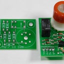
Introduction: Custom PCB Prototyping Using a Laser Cutter
I am going to walk you through the process of prototyping a Printed Circuit Board using a laser cutter and supplies from your local Radioshack and hardware store. This is a process I have perfected after several prototypes I created as part of my thesis, modular//neuroid.
Step 1: Prepare the Board
Remove the bare copper PC Board from the plastic being careful not to get oily fingerprints on it. Place it on a clean, suitable spraying surface (newspaper or cardboard are great). Using flat black spray paint (I used Krylon brand) coat the copper 3 - 5, allowing time for each coat to dry before applying the next. If your PC Board is double sided, be sure to repeat this step for the other side. By the end of this step, your board should look completely black, no bumps or unevenness, and certainly no copper visible at all.
Step 2: Prepare Your File
Most laser cutters use vector files to print. Ours (an Epilog Legend 36 EXT) can print PDF or Adobe Illustrator files. To build a correct schematic, export the footprint of your components (in this case female mini-USB ports) as vector files from Eagle or Fring. Import this to Illustrator, and build your own traces. Keep in mind a few things:
• we want the laser cutter to burn away everything that is NOT a trace, therefore the background is black and our circuit is white.
• 1.5pt lines are the smallest that can be drawn
• For text, no smaller than 5pt font, and should be placed as a negative inside of a box, otherwise it will get etched away
• If you are making double sided boards, finish your front side and then mirror. This is the easiest way to keep things lined up with each other.
• Be as efficient as possible : cram as many as you can together, it will make cutting boards later easier as well
Step 3: Go Laser Go
Laser your file. The strength and speed of the print will depend on your specific machine. On ours, medium speed with high power were the best settings. Also keep in mind the number of coats you used. The only thing to keep in mind when setting the print : laser bottom to top - top being the side with air vacuum. This way the vaporized paint won't re-coat already lasered areas.
Definitely avoid re-lasering a second time over. There's pretty much no way to avoid having to do this if you notice you haven't gotten all the way through the paint, but once you figure out your settings, remember them so as to avoid having to do a twice-over.
Step 4: Clean Up the Board
Now as you can see, the result of the lasering is beautiful, however we are not ready for etching just yet. There is a very thin layer of paint residue left on the copper that will block the etchant solution from working properly, and will slow that process down a lot. Here's what to do : Soak one end of a q-tip in rubbing alcohol (ethyl or isopropyl) and spread it on the exposed copper. Try to keep it off of the black paint, because we want that to stay. Use the other end of the q-tip to rub away, essentially polishing off the copper, making it shiny and ready for etching. You can see in the second image, the board on the far right has been cleaned, and is shiny and ready to go.
Step 5: Cut Boards and Etch
It is really your choice to cut the boards first or etch the entire board and then cut it afterwards. I feel that you need less solution and a require a smaller container if you cut the boards first, and then etch afterwards. With Radioshack's Etchant Solution (Ferric Chloride), you only need to use a little more than enough to cover the boards entirely. Once the boards are submerged you need to "agitate" them for about 20 - 30 minutes. "Agitate" really just means move around -- I simply lifted and dropped one end of the container every 10 - 20 seconds. Nothing rough, just a slow wash. After about 5 - 7 minutes you will begin seeing the orange copper disappear and the yellow color of the fiberglass underneath start to come through. By the 30 minute mark there should be no more orange copper, only black lines on yellow. You are done. As the bottle says, flush the excess solution, and rinse the boards with water in a sink. The solution will stain, so be careful. It will also smell of a bizarre and unpleasant musk. This is normal if you use ferric chloride.
Step 6: Clean and Polish
using a paint remover such as Xylene or paint thinner, bathe or wipe the remaining black paint off of the boards. It will get a bit dirty (as will your hands) but keep polishing and you will get the boards clean, leaving just your brilliantly designed circuit. Success!
Step 7: Solder and Wire It Up
Here's my USB breakout board (prototype 0.3) ready for testing.
Step 8: Repeat!
That wasn't so bad. You'll notice that not all of them come out perfectly. The way the paint dried, the laser settings, all have effects on the final boards. You'll learn, and make it better next time. Eventually the circuit will be perfected, and you can pay a boardhouse to do all this for you!


