

Introduction: Model Railway - DCC Command Station Using Arduino:


Updated August 2018 - see new Instructable:
https://www.instructables.com/id/Model-Railroad-DC...
Update 28th April 2016:
Now 16 turnout / points control capability to Command Station.
The turnouts T1 - T8 are available via 'B' key
The turnouts T9 - T16 are available via 'C' key
Update 10th March 2016:
Now added 8 turnout / points control capability to Command Station. The Arduino code has been updated accordingly using the NMRA standard packet for turnouts (also based on a study of Lenz / Atlas Compact data packets for turnout control).
The turnouts T1 - T8 are available via 'B' key
See instructable on the data packet receiver circuit used and Arduino code required.
Update 18th Jan 2016:
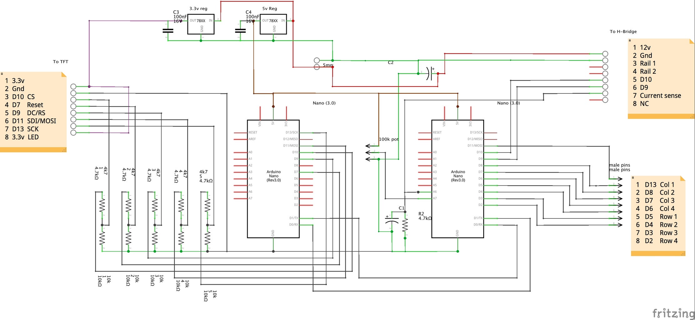
I have added a current sense resistor (1k5 ohm) and capacitor (10 uf) to the circuit and amended the Arduino code to cut off power when a peak current of > 3200 mAmps is detected. The H-bridge spec states an output sense current of 377 uA per 1 Amp in the load.
The 1.5 k ohm resistor will deliver 0.565 volts per Amp on the analog pin 6. With 1023 steps on the analog input, this gives 0.565 * 1023 / 5 = 116 per Amp load.
A = 100 * (analogRead(AN_CURRENT)) / 116;
A = A * 10; (to give result in milliamps)
The load current in milliamps is displayed on the TFT
The full 4x4 keyboard includes F1 to F8 functions and another 10 locos (1-19) through the '#' key (to add 10 to the numeric keys starting from loco 10).
The arduino code includes the NMRA standard for instruction bytes.
See link
http://www.nmra.org/sites/default/files/s-9.2.1_20...
(page 6 is of particular relevance)
The packets are arranged according to number of speed steps, long / short address and Function Group instructions.
All instruction bytes are preceded by a preamble of '1' bits 11111111 (or idle packet) followed by;
e.g. A 4 byte address 0 00000011 0 00111111 0 10000011 0 10111111
equates to loco 3, 128 speed steps, forward direction and speed step 3 (the end byte is the error check XOR)
e.g A 3 byte address 0 00000011 0 10010000 0 10110011
equates to loco 3, function group 1, FL lights on plus XOR byte ( a '0' bit separates each byte)
See enclosed demonstration video for loco 12.
The functions F1 - F8 are available via 'A' key, DIR ('*' key = direction) FL ('0' key = lights) and key '#' gives locos 10 to 19 on the numeric keypad. The 'D' key is now used for an 'Emergency STOP'.
Thanks to various providers on the web for sources of DCC information and Arduino code.
In particular, this project was inspired by Michael Blank and his 'Simple DCC - a command station'
http://www.oscale.net/en/simpledcc
4x4 Matrix Array 16 Key Membrane Switch Keypad (ebay) £1.75
2.2 inch 240x320 Serial SPI TFT LCD Display Module (ebay) £7.19
UNIVERSAL 12V 5A 60W POWER SUPPLY AC ADAPTER (ebay) £6.49
Nano V3.0 For Arduino with CH340G 5V 16M compatible ATmega328P (ebay) 2 x £3.30 = £6.60
Motor Driver Module LMD18200T for Arduino R3 (ebay) £6.99
Connectors, wire, vero board, potentiometer approx £3.50
Total £32.52
The basic command station without tft screen and 1 x nano would be £22.03
[Note : It is possible to add a memory card to the TFT display and amend code to display images of selected engines, although the library codes must be edited down to create more memory for the sketch. Current sketch size is at a maximum for the TFT Arduino Nano]
The original Arduino code by Michael Blank was for one engine, forward / reverse only with no function control, no keypad and no display.
I have modified the code to include 1 - 19 engines, a display screen, direction, lights, 8 functions, emergency stop and auto current limit.
The LMD18200T bridge can carry up to 3 amps which makes it suitable for all scales including G-scale (garden trains). The mains power supply and electronics are suitable for indoor use only unless you can make it all weather proof. I have the command station in the summer house with rail connecting wires running out through the wall to the track.
Step 1: Arduino Code - Command Station With Keypad
My thanks to tvantenna2759 for pointing out 2 errors in the circuit diagram where the Arduino code did not match the wiring, now updated (21 Oct 2017).
Now added 16 turnouts to Command Station. See instructable on the turnout / points circuit diagram using Arduino Mini Pro module.
The modified code including turnout control is attached below.
Basic Accessory decoder packet is :
0 10AAAAAA 0 1AAACDDD 0 EEEEEEEE 1
From analysing the packet used by Lenz (Compact / Atlas) for points control, I have used the following binary packet format for bytes 1 and 2 :
tunAddr = 1
Turnout 1a : 1000 0001 1111 1000 / Turnout 1b : 1000 0001 1111 1001
Turnout 2a : 1000 0001 1111 1010 / Turnout 2b : 1000 0001 1111 1011
Turnout 3a : 1000 0001 1111 1100 / Turnout 3b : 1000 0001 1111 1101
Turnout 4a : 1000 0001 1111 1110 / Turnout 4b : 1000 0001 1111 1111
tunAddr = 2
------------------------------------------------------------------------------------------------------------
Turnout 5a : 1000 0010 1111 1000 / Turnout 5b : 1000 0010 1111 1001
Turnout 6a : 1000 0010 1111 1010 / Turnout 6b : 1000 0010 1111 1011
Turnout 7a : 1000 0010 1111 1100 / Turnout 7b : 1000 0010 1111 1101
Turnout 8a : 1000 0010 1111 1110 / Turnout 8b : 1000 0010 1111 1111
-----------------------------------------------------------------------------------------------------------
Turnout 9a : 1000 0011 1111 1000 / Turnout 9b : 1000 0011 1111 1001
etc .........
Extract from modified code:
Add 2 more 'struct' message updates
void amend_tun1 (struct Message & x)
{
x.data[0] = 0x81; // accessory decoder 0x80 & address 1
x.data[1] = 0;
}
void amend_tun2 (struct Message & x)
{ x.data[0] = 0x82; // accessory decoder 0x80 & address 2
x.data[1] = 0;
}
Add new void for turnouts:
boolean read_turnout() {
delay(20);
boolean changed_t = false;
get_key();
if (key_val >= 101 && key_val <= 404 && turn == 1){
data = 0xf8; // = binary 1111 1000
amend_tun1(msg[1]);
}
if (key_val >= 505 && key_val <= 808 && turn == 1){
data = 0xf8; // = binary 1111 1000
amend_tun2(msg[1]);
}
if (key_val == 101 && turn == 1){
if (tun1 == 1 ){
data |= 0; // t1a
changed_t = true;}
if (tun1 == 0 ){
data |= 0x01; // t1b
changed_t = true;}
}
if (key_val == 202 && turn == 1){
if (tun2 == 1 ){
data |= 0x02; // t2a
changed_t = true;
}
if (tun2 == 0 ){
data |= 0x03 ; // t2b
changed_t = true; }
}
if (key_val == 303 && turn == 1){
if (tun3 == 1 ){
data |= 0x04; // t3a
changed_t = true;
}
if (tun3 == 0 ){
data |= 0x05; // t3b
changed_t = true;}
}
if (key_val == 404 && turn == 1){
if (tun4 == 1 ){
data |= 0x06; // t4a
changed_t = true;
}
if (tun4 == 0 ){
data |= 0x07; // f4b
changed_t = true;}
}
if (key_val == 505 && turn == 1){
if (tun5 == 1 ){
data |= 0; // t5a
changed_t = true;
}
if (tun5 == 0 ){
data |= 0x01; // t5b
changed_t = true;}
}
etc ......................
Attachments

Step 2: Arduino Code - TFT Display


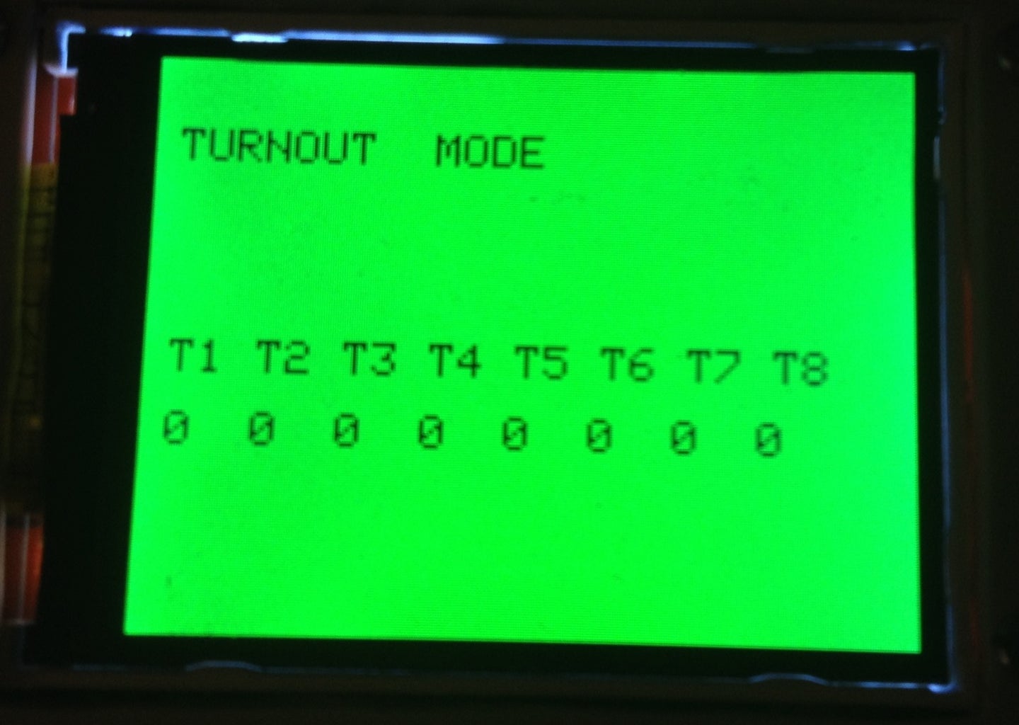
The display circuit remains the same with a modified code to show the status of the 16 turnouts. Note: The library code takes up nearly all of the sketch code memory leaving little room for new features. If anyone has a more efficient library file for the TFT used here, please let me know.
Attachments
Step 3: Turnout Controller

See instructable on how to make the Turnout / Points controller.
The complete circuit controls 16 points and 15 accessories such as lights, sounds, turntable, etc.

Participated in the
Arduino All The Things! Contest


