

Introduction: DIY 3D Printer Enclosure


I have been the proud owner of a RepRap 3D printer for a few years now, and while its been extremely handy for rapid prototyping I figured it was about time for some upgrades. First thing on my mind was to build an enclosure for the Velleman K8200 model I had been using. There are definitely a number of benefits to an enclosed 3D printer rather than the standard open RepRap layout, which include:
- printer is able to maintain a near dust free environment
- heat is far more regulated
- quicker heating of print bed and hot end
- noticeable noise reduction (my printer is in my bedroom and I now have no problem starting a print and going to sleep)
- a dust free air tight environment for filament spools (optional but something I did include in my design)
- a ton more surface area for add ons such as lights and other accessories
Hopefully this gives you an idea of what worked and didn't work as well for me. This is version 1 and was built relatively quickly. Luckily I had access to a variety of tools to make the job a bit easier but this can be done with somewhat limited resources.
Here is a link to the original Velleman K8200 Printer Kit:https://www.vellemanstore.com/en/velleman-k8200-3d-printer-kit
Step 1: Design Ideas


Lets start by talking about the design.
During the design process there were a few key properties I was keeping in mind:
- An enclosure that was as efficient with its space as possible
- Easy ability to observe and make adjustments
- An enclosure as air tight as possible to keep heat in and keep dust out
- An even more air tight enclosure for filament to keep filament from becoming brittle when exposed to moisture
- Lastly I wanted to create an enclosure that increased printing efficiency by being ergonomically sound, in other words very simple to operate.
I drafted and rendered a design with Autodesk Fusion 360 as seen above. The dimensions were just a bit bigger than the original K8200 frame so it could include the power supply and electronics inside. I decided to go with a solid enclosure with a plexiglass door/viewing window so prints could be assessed without having to open and bring down the ambient temp of the enclosure. A few months ago I replaced the driver electronics on my K8200 with a RAMPS 1.4 kit with LCD display so I included an area to mount the LCD as well and a SD card slot and multiple USB input areas. Also in the bottom left corner would be a master power switch. While working on the design I noticed the K8200 left a large area behind the frame supporting the Z axis unused and decided to try to fit in a separate air tight enclosure for filament. The only openings to this chamber would be an insulated door on top and some PTFE tubing going straight into the extruder/hot end inside the main enclosure.
Step 2: Building Materials
For the over all structure of the enclosure I considered a few different materials. First thought was to build the entire casing out of plexi/acrilic, but I was also attempting to keep the price of the build as low as possible. I settled on building a frame out of solid wood (happened to be Madrone wood but only because it was available) and then enclosed that frame with some 1/4in MDF. The 1/4in MDF I used was from Home Depot and came with a side coated in a marker board finish, which after painting gave the exterior walls of the enclosure a nice plasticy looking finish. Along with the material for the overall structure I used 1/4in plexiglass for the door/viewing window, some weatherstrip door seal to create a close to air tight seal when the plexiglass door is closed, some 90-degree Surface Mount Hidden Spring hinges, and other random hardware. I have also wired an LED strip light to directly to the power supply to make viewing much easier inside the enclosure while power is on. I will include everything in list formate below.
Lengths/Dimensions of materials vary proportionally to overall dimensions of enclosure
- lengths of 1/2in x 3/4in solid wood for frame
- 3 or 4 24in x 48in sheets of 1/4in MDF (marker board coated optional) available at Home Depot
- 24in x 24in sheet of 1/4in plexiglass or acrylic
- weather strip door seal (to seal the plexi door when closed) also available at Home Depot
- 2 90-degree surface mount hidden spring hinges
- cabinet/drawer handle hardware
- LED strip light with 12v driver (mine has an IR remote that allows me to change the light color which is a cool touch)
Randome Hardware and fasteners
- wood glue
- pin nails
- nuts and bolts for hinge/door handle
- some sort of adhesive or super glue is always handy too
Step 3: The Frame


Before I get started explaining the build let me clarify something. My view is if you own a RepRap 3D printer and are looking to make upgrades such as a heat enclosure you are assumably an inspired and capable maker. This instructable will not be an exact step by step recipe to duplicate my build, but rather a rundown of my experience to give inspiration and guidance to anyone interested in something similar. While that be the case if more details are needed I would love to help out so feel free to reach out. In addition, new design ideas are welcome and appreciated. I defiantly see myself building version 2 sometime in the future.
Back to the build!
I decided to start with a hard wood frame for a few reasons. One being that it would be extremely difficult to create a structurally sound box out of 1/4in MDF with no kind of internal supports. Rather than having to pin nail the 1/4in MDF to other MDF pieces it allowed me to pin all the walls to the frame which had a considerable amount more surface area. As you can see from the picture included, the frame includes an area that will be a separate enclosure for the filament spools. At most joints I included blocks to further increase the rigidness of the structure and fastening was done by applying wood glue and immediately pin nailing with a nail gun.
*POINT OF LARGE IMPORTANCE*
Make sure every aspect of the frame is square in relation to all three dimensions. Your MDF panels should be near perfectly square so adding square panels to a frame that is not square will create unnecessary challenges. Using a large T-square proved very helpful.
Step 4: From Open Frame to Enclosure


Once the frame is complete its time to cut and fit the MDF panels onto the frame. I tried to keep the maker board finish facing outward as often as possible to have the painted finishes match after painting. This is a pretty simple/self explanatory step, you are just pin nailing/glueing the MDF panels to the frame. While cutting the MDF panels on the table saw I was at first cutting a 45-degree bevel on every edge to fit the panels together flush, but after painting, the rough cut edge of the MDF isn't a big deal, so looking back it seemed like and unnecessary touch. Also you can just add some sort of 90-degree edge trim if you want to clean up the panel joints.
Not only do you need to enclose the outside of the frame but add MDF panels to create the separate filament enclosure. Using some silicone caulking on the filament enclosure will ensure moisture stays out and your filament stays as fresh as possible. *Side Note* I usually just drop the moisture absorber packet that comes with a new spool of filament into the filament chamber to further protect the filament from moisture.
I decided to make a design change on the fly by including a plexiglass window from the main enclosure chamber into the filament chamber just to be able to make sure the filament spool is unwinding smoothly and being able to see the filament levels and color without having to open the filament area at all. This was done by using a spare piece of plexi and using a jig saw to cut out a rectangle in the panel that is in the same plane as the front viewing window.
*POINT OF LARGE IMPORTANCE*
[On any of these cuts that will have plexi glass inserted, it is far better to not cut off enough material for the plexi to fit than to cut too much and have a loose fit. You can always take off more material little by little but using shims to secure the plexi in place is not ideal.]
The more difficult part of this step is to draft and cut the front panel and plexiglass door. Obviously the 3/4 radius rounded corner I added to my design are not necessary but definitely added aesthetic appeal. I drafted the overall shape of the cutout for the door on the MDF panel then used a compass to add the rounded corners. I then used a large drill bit to drill a whole in each concave corner to have a starting point for the jig saw. Using a guide for the jig saw to cut along definitely helped to get straighter cuts. Clamping a ruler parallel to the cut would work fine as a guide. To finish up the face panel I cut areas for the RAMPS 1.4 LCD screen and ON/OFF switch/usb input. These last cuts weren't as important to get exact because I planned on printing covers for the LCD and switches to trim out these holes.
- From the hard part of this step to the harder part of this step! -
After finishing the front face MDF panel I used it to trace an outline onto the plexiglass that would eventually become the door/viewing window. Because I planned on adding the weather stripping to the inside edge of the front panel I need to take about and extra 1/4in off every side of the plexi cutout. This is a similar cut to cutting the front MDF panel just scrapping the outside instead of the inside of the cut. The increase in difficulty comes from dealing with the different material. Cutting plexiglass with a jigsaw heats the plexi so much that in many cases the melted plexi behind the blade re-adheres to the piece being cut thus warranting a second run-though with the jigsaw to separate the two pieces. Of course clean up of both the plexiglass and the panel it inserts into will be needed. Sand paper works fine on the plexiglass, just try to avoid scratching the flat surface of the plexi.
Step 5: Painting and Attaching Door


Obviously painting is optional, I chose to spray the whole thing black, the marker board finish on the MDF gave it a nice plastic look after painting. I actually used plastidip spray paint which actually adds a plastic coating. The down fall is that plastidip is removable so it peels of slick surfaces. In hind sight it might have been better to just use a flat black multipurpose spray paint.
After painting is finished or skipped add the weather proof strip to the front panel. I modified the stripping a bit to form a T shape strip by cutting off a bit of it. Leaving a solid over hang for the door to rest on when closed and creating a near air tight seal. I attached the stripping with a strong adhesive and made sure to let it cure before moving on to attaching the door.
It is a good idea to drill holes for the the door handle hardware before attaching the door to the enclosure. I chose the hinges so everything could be inside the enclosure once again mostly for aesthetic appeal. Any hinges that fit and have around 90-degree range of motion would work.
Step 6: Incorporating Electronics With Printed Parts


Now for the fun part! Dressing it up and making it look nice!
There are 4 main printed parts on the enclosure right now (along with others on the actual printer). Those include:
- The frame/mount for the LCD display and SD card slot
- The mount for the master ON/OFF switch and USB input
- The mounts to hold a 1in diameter aluminum tube to suspend the filament spool
- A vent to prevent electronics from over heating
Lets start with the RAMPS 1.4 LCD and SD car mount.
I had to desolder the SD card slot mounted on the back of the LCD and add extension ribbon cable to be able to mount the slot in an accessible area under the LCD. This is certainly not necessary seeing how the original board on the K8200 didn't have an SD card slot and I haven't used it since I've had it available. Only benefit is being able to print without the assistance of a computer. The perimeter of the printed panel is adhered to the face of the front panel of the enclosure.
The ON/OFF switch and USB input
The on/off switch I used interrupts the load wire straight from the wall outlet before it reached the power supply for the printer. It also has a 3V LED indicator light that indicated that the power supply is on so I used a 3.3V regulator to step down the 12V of the power supply to power that indicator. The USB input is actually two PCB mountable Female USB ports connected to each other so I could have a USB cord coming in and also a simple usb cord going from the outlet to the RAMPS 1.4.
The Spool Mounts
These are very simple pieces. Just use some sort of strong adhesive to mount them inside the filament chamber.
The Vent
In the picture on here the vent isn't on, its just an open frame for the vent hole to be able to access the electronics easily. I will be running wires off my 12v 30a power supply from the built in fan output that responds to temp so a 60m x 60m fan will engage when the power supply temp gets too high.
Last piece of electronic that need to be installed is any kind of lights to illuminate the inside of the enclosure. Like I said in the Building Materials section, I chose to go with a LED strip light with a 12V driver that draws straight from the power supply so as soon as you hit the master ON/OFF switch the printers internals are illuminated very well. A benefit of having the strip of LEDs is that having an array eliminated shadows and disperses the light well around the whole enclosure.
Step 7: Final Product Review


Thats about it for this particular upgrade!
Im very happy with the look as well as the functionality. I have definitely noticed improvements in all aspects i was hoping for. Print quality has increased due to regulation of heat and the prep time for a print has decreased considerably.
I will include links to STL files for all printed parts. Most were made in 123D design so I can provide the full file if you would like to make modifications to it. Hope this inspires new ideas and helps anyone who is interested in something similar.
Lastly there are a variety of other upgrades I have made to my original K8200 RepRap including:
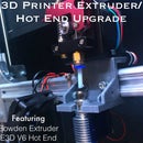
- K8200 Extruder/Hot end replacement with an E3D V6 Hotend and A Bowden Extruder
{ This upgrade has produced incredible results in print quality and print speed }
- In progress* Adding a Rotary Attachment to the printer to be able to engrave multiple materials and etch PCBs
I will provide instructables for both of these new upgrades as soon as possible. Any positive feedback from this first one will likely increase my urgency of getting the next done.
Thanks for checking this out!

Participated in the
3D Printing Contest 2016


