

Introduction: DIY 5 Volt USB Car Charger (buck Converter)


I know, there are many USB car charger sold in stores around, and they are also cheap...but why don't make one by myself, wich can be compared to them?
Also, at minimum expense...
That is, as for me, 0.60 € for the white electric box, and 2,00 € for the cigarette lighter plug. For those who do not have it, the cost for the IC is about 2 €.
Step 1: The DC-DC Converter


The core of the project is the L4962 IC.
It is a 1.5A monolithic power switching regulator, operating in step down configuration.
It can be in the form of the POWERDIP, that is L4962/A, or the HEPTWATT VERTICAL, the L4962/EA. I used the latter, since a small heatsink can be mounted on it, if necessary.
Also, I thought to use this one because I had a couple (obtained from an old PSU circuit) and I wanted to exploit its potential...like to charge a phone, for exemple, when you are outdoor with the car.
The IC probabily is not well known, maybe it's a little obsolete but it's not so rare around. And taking a look to its datasheet one can see that it is quite efficient, almost such as those more recent.
Also has a much better efficiency compared to the commons voltage regulators, like L7805-7809 etc, namely from 70% for the minimum input voltage (that is 9 V) up to 80% for higher voltages, in comparison to about 50% of the voltage regulators.
Finally, it can operate in a wide range of voltages (from 9 to 40 V) and with a quite high switching frequency, up to 150 KHz, allowing you to build small and compact circuits.
Step 2: The Circuit for 5.1 V Output


Here is the diagram for the circuit.
The regulation loop consists of a sawtooth oscillator, error amplifier, comparator and the output stage.
An error signal is produced by comparing the output voltage with a precise 5.1 V on-chip reference (Zener). This error signal is then compared with the sawtooth signal to generate a fixed frequency pulsed width modulation, which drive the output stage.
The gain and frequency of the loop is set by an RC network to pin 5. When the loop is closed directly by connecting the supply output to the feedback input of the IC pin 2, an output voltage of 5.1 V is then produced.
Higher voltages can be obtained by inserting a voltage divider in the feedback network.
The IC provides also an output overload protection in the form of a current limiter, and a thermal protection which disables operations when the junction temperature is about 150°C.
In the PHOTO 2 there is the final circuit assembled on pcb. I will show how to do in the next steps...
Step 3: Materials and Components

The materials I used are:
- L4962/AE (Heptawatt) - (U1)
- 1/4-watt resistor 220 Ohm (for the led); 1/4-watt resistor 15 KOhm; 1/4-watt resistor 4.7 KOhm - (R1, R2, R3)
1 capacitor 33 nF and 1 of 2.2 nF (ceramic) - (C5, C6)
- 2 electrolitic capacitors 220 uF (35 V) - (C2, C3)
- 1 eletrolitic capacitor 100 uF (50 V) - (C1)
1 eletrolitic capacitor 22 uF (50-100 V) - (C4)
- 1 Schottky diode, like 1n5822,SR360 ecc - (D1)
1 rectifier diode, like 1n4007 - (D3)
- USB female connector
Toroidal ferrite core (0.5-1 inch diam.), for example a FT-50 - (L1)
Magnet copper wire ~26 AWG
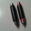
Cigarette Lighter Plug with cable
- 1 red led (small) - (D2)
- Some electrical wires, different colors for +/-
- Soldering iron, tin solder
- A piece of previously etched PCB board, where components are mounted
- Some pieces of wood or other material, where USB and the main circuit can be screwed
A suitable case where insert all the elements (mine is a small electrical box bought in a big hadrware store)
- Cutter, sandpaper, glue...
PS: Component symbols are associated with the circuit diagram of the next step
Step 4: The Complete Circuit and the PCB Layout


In the first image is shown the complete circuit for the car charger (See previous step for details).
From the image, in addition to core of the circuit of the IC, one can see I put a red led between the output and the USB connector that must light up when cigarette lighter plug is inserted; and a rectifier diode before the input voltage, in order to prevent the event of a negative voltage.
About the PCB layout, I present a possible solution for the routes (IMAGE 2) where the input, the ouput and the ground are differently marked.
.
Finally, as it appears my PCB square after acidic treatment (PHOTO 2-3).
Step 5: Mounting the Different Parts Into the Box


First, I drilled on one side of the main PCB, in correspondence of the copper track on the ground, and made it firm with a screw on a rectangle of plywood, leaning on the base of the box.
The following operation is to "join" the USB female connector as near as possibile to wall of the box, via a couple of strips of plywood and then it has been practiced a hole between the lid and the box (particular in the last PHOTO), to make possible the passage of USB male connector. Of course, nothing prevents you can use other materials, maybe most suitable. I chose them for practical reasons
To make the USB connector stable and fixed, I glued the two small strips of plywood at each other (so that they are L-shaped, SEE PHOTO 3-4) and I fastened the USB base to one strip through a small screw.
At this point, the main PCB and the USB structure are bound together, and the USB connector is shored up by a stick, so as no part is being able to move.
Similarly to the LED, I practiced a hole on the lid of the box, at the center, then soldering the 220-ohm resistor and glued the LED to the plastic.
The steps with the various parts assembled together are shown in sequence...
Step 6: Finishing the Job


After shortening not needed pieces of wire, I soldered the output terminals of the main circuit to the LED, respectively, and to the USB connector.
At the other side, I soldered the 1n4007 diode between the 12-V plug and the input of the IC's circuit.
I added some heat shrinkable electrical tape, where required.
The branches of the input and output circuit so obtained are as shown in the images.
Step 7: Testing the Charger


This is the final result.
We just have to try the behaviour of the circuit...so first I connected to a 12-V mobile phone charger, verifying the lighting of the LED and the voltage in the stable output at 5.1 volts for a while, as expected from theory.
The next thing I did was to connect to the DIY charger my old Samsung....and it worked (SEE PHOTO). As last step, I recharged my smartphone through the 12-V car receptacle. I didn't wait a full charging, but after some time I could observe a fair increase of the charge percentage from the display .
The other noticeable fact is that despite having left the heatsink out the IC hasn't warmed up, making it a worthy substitute of traditional voltage regulators...


