

Introduction: DIY 8 X 8 LED Matrix With Controller


I'm in the process of making a Word Clock, and one of the things that I wanted to build for this project was a fairly simple 8 x 8 LED matrix.
This instructable deals with how to build an 8 x 8 LED matrix and controller that can be interfaced with an Arduino microprocessor.
Parts:
- 64 LED (I'm using 5 mm White LED with a forward voltage of 3.5 V and a load of 20 mA);
- 1 10 uF electrolytic capacitor;
- 1 x 0.1 uF ceramic capacitor;
- 1 x 10 k ohm resistor;
- 1 x MAX7219CNG Serially Interfaced, 8-Digit LED Display Driver;
- lots of wire
- plywood and 10 mm pine for case and matrix body
- 800 GSM card for cells
- 1 Arduino Uno
One of the things that I found a little frustrating was that I couldn't find an example of what I was trying to do on the Interweb. Oh, sure ... there were plenty of examples of how to make a controller for your prepackaged Dot Matrix Display, etc., but nothing that showed me the whole enchilada.
Step 1: Matrix Body

The body is made of a plywood board (210 mm x 210 mm), a lattice of card cut from 800 GSM card, white paint and white glue. I've also made a frame around the matrix from 10 mm pine strips (200 x 10 mm).
First, I created an 8 x 8 table in MS-Word and set the Row and Column height/width to 2.5 cm and then printed it out on my printer. I cut around the printed table and glued it onto a sheet of 6 mm plywood. When the glue was dry, I cut out the grid using a jigsaw.
The second stage was to mark the center of each cell and drill a 5 mm hole in the middle of each.
The lattice was made by cutting 20 mm x 200 mm strips of card from the 800 GSM stock and then cutting 1 mm slots into the strips so that I could slot the strips together to make a grid, much in the same way that you find wine bottles separated in cardboard cartons. The slots were cut 1 mm wide so that they would allow the opposite strip to fit easily. The lattice was glued together and another 4 x 201 mm pieces were cut to provide a border (with a 1 mm overlap).
After the glue had set, I glued the lattice to the plywood, using the printed grid as a guide for the lattice.
I laid the matrix down upside down on my workbench and weighted it down with a number of thick text books so that the glued and cured matrix would be very even.
I found that the matrix could easily support 10 kg of books, so I guess that it's pretty strong.
Where the slots were a little loose and allowed light to get from one cell into the neighboring cell, I cut a small piece of paper and glued it over the gap on both sides. This meant that the amount of light that can get through is minimized (but not eliminated).
Step 2: LED Wiring - Rows and Columns

As with all good LED matrices, this is achieved by soldering columns of anodes and rows of cathodes together. You will end up with 8 rows of cathodes and ... 8 columns of anodes.
I used 18 gauge solid core copper wire to make the rows and columns and simply soldered the row cathodes to the row copper wire and then the column anodes to the column copper wire. At each junction, I slipped a small piece of shrinky tube over the wire wherever it crosses the opposite plane (row or column).
I then soldered 16 leads onto the matrix (8 x red for anodes and 8 x black for cathodes). DuPont male connectors were added to the end of each lead so that I could connect it to the LED Controller later on.
Using my trusty multi-meter switched to continuity test mode, I then tested each combination of anode to cathode to make sure that only one LED lights up at a time when only one anode and one cathode are probed.
I labelled each column of anodes with numbers (1 - 8) and each row of cathodes with letters (A - H)
Because of my zealousness with shrinky protection, this all went pretty well and the matrix tested out perfectly.
There really isn't an adequate substitute for planning and testing ... it saves time, effort and frustration.
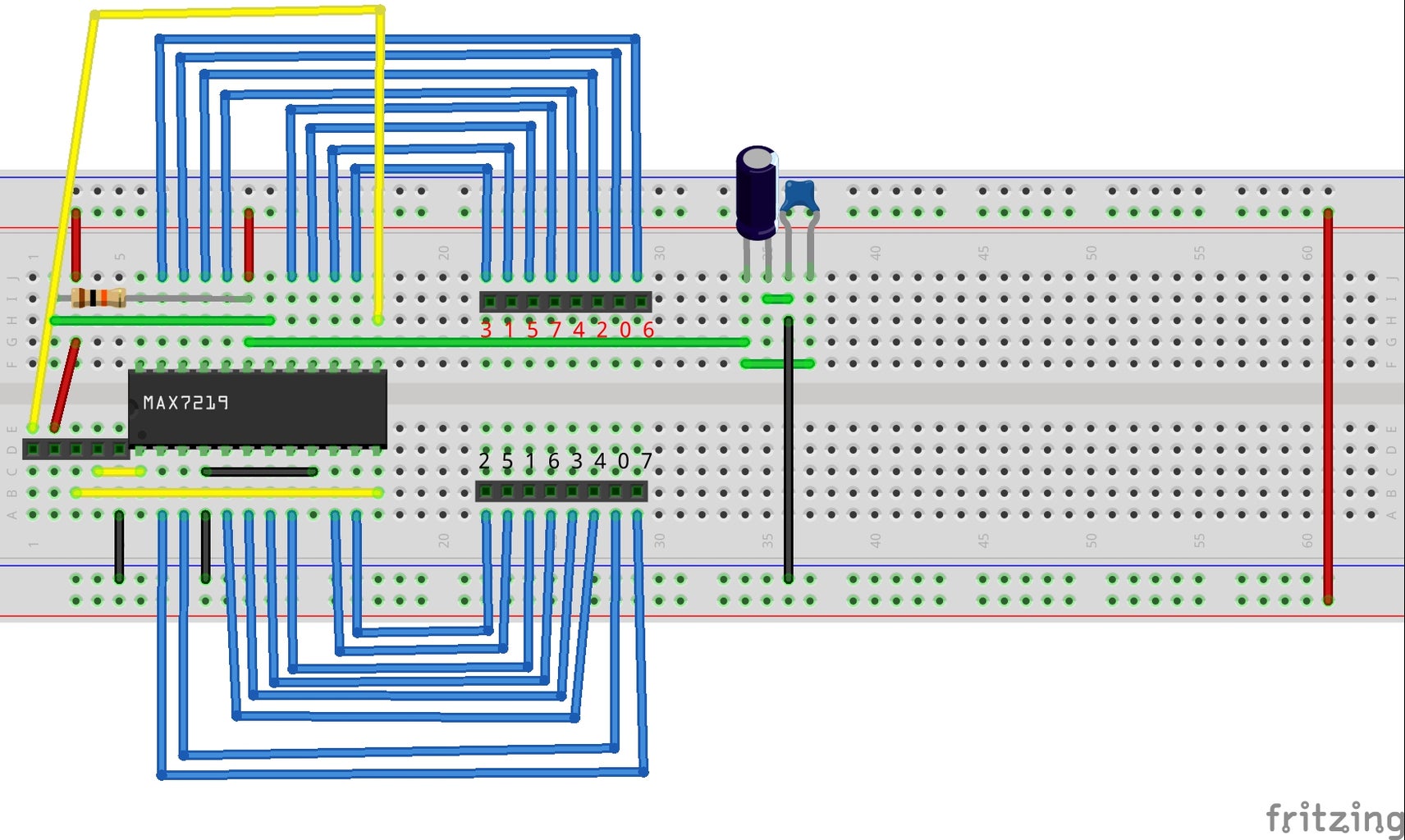
Step 3: LED Controller Wiring


The LED Controller is using a MAX7219CNG chip to handle the rows (DIG0 - DIG7) and the columns (SEGA - SEGG).
The MAX7219CNG is a very easy to use chip and it requires very few additional pieces:
- A resistor to provide a common current limit, in my case I'm using a 10 k ohm resistor;
- A 10 uF electrolytic capacitor and a 100 nF ceramic capacitor used to smooth the current supply;
- jumpers to connect your controller to your LED matrix
I have provided a breakout header to connect the circuit to an Arduino to provide processing for the controller.
Were you so minded, you could also provide an output header so that you could daisy chain multiple controllers/LED matrices together ... I'm not.
When I connected the LED matrix to the controller, I had to work out which anode connects to which SEG and which cathode connects to which DIG. I did this by the simple (but time consuming) expedient of writing a sketch that only switches one LED at a time and then poking the row/column in to the connections until I had the correct LED lit up.
I have labelled the breadboard schematic as well as the PCB design with the resulting pin connection(s).
I am waiting for my Real Time Clock module at the moment, and I will fabricate the printed circuit board when I have that in hand. I want to make the circuit board so that it incorporates a customized DIY-Arduino and the Real Time Clock into one circuit-board. I also need to add some buttons to the DIY-Arduino so that I can set the time on the clock ... but that's an article for later.
Step 4: Test Sketch

I can't take very much credit for this at all ... this is the LEDControlMS sketch that comes with the LEDControl library. All I've done here is to change the loop with the lines:
//  setLed(add, row, col, bool state)
//  lc.setLed(0, 6, 0, true);
lc.clearDisplay(0);
These lines were used for controlling which LED is lit so that I could work out the row/column output for my matrix.
Once I had gone through the 16 pins, I then commented the added lines and allowed the sketch to run.
I was pretty pleased with the results, although the writeArduinoOnMatrix() function didn't seem to work ... I probably need to investigate that further, but for the purposes of the LED Matrix and the planned Word Clock, it isn't necessary.
Anyway, that's it. A pretty simple custom LED matrix using a MAX7219CNG chip.


