

Introduction: DIY Aluminum 3-AXIS CNC Router


This is a CNC I built from scratch using mostly 3/4" x 3/4" x1/16" aluminum square tubing. I got the design by looking around for ideas on Google and mostly just improvised as I got to each phase.
The total cutting area is about 12" x 8" x 3" (X by Y by Z).
The rails and bearings required over 100 5/16" nuts.
I estimate that the whole thing cost approximately $650-$700 to build including Ontario taxes.
Note: I built the whole thing with a regular hammer drill (which has a switch to become a normal drill), a hack saw, and a jig saw. I had no drill press or chop saw that made perfect cuts/holes. Of course a drill press and chop saw would make the whole thing go a lot faster than it did for me.
In each step of this instructable, I will show what individual components I used.
If enough people (or any at all) want to build one like this then I will use SketchUp to create some plans. But for now, this is really just to give some ideas on how to build one yourself.
PLEASE CHECK OUT THE VIDEOS OF SAMPLE WORK AT THE END.
Step 1: Main Frame


The pipe is 3/4" galvanized steel pipe.
I spray-painted the frame matte white to make it look a little more pleasing. I am happy with how the finish turned out.
The length of the pipes are not so important so long as you have good clearance for all the axes.
It is important for the diameter of the pipe to be sufficient if the pipes are long. I have had to fasten the neck of the Z axis to the wall to restrict deflection.
Step 2: Bearings

I used bearings that have a 8 mm bore, 22 mm outer diameter, and are 7 mm thick.
Note the inner diameter of 8 mm is just slightly larger than 5/16" of an inch. When bolting these to the linear bearing assemblies, the nuts will tighten enough that the difference in diameters won't matter (i.e. the bearing is as tight as if an M8 bolt was used).
Step 3: X Axis


The X linear rails are approximately 26" long and are spaced 15" apart from the inside parts of the rails.
It may seem as if the whole "carriage" is only held down by gravity, but the bearings on the side actually squeeze the rail quite tightly and leave a black stain.
The X axis and Y axis are built together as one assembly.
The Y linear rails actually help the four X bearing blocks (I'll use blocks for the lack of a better word) stay square to each other.
Step 4: Y Axis


The Y bearing assemblies are turned sideways with respect to the X axis. I attempted, at first, to orient them the same as the X axis, however, the major issue was the length the aluminum blocks had to be. Because of the design I chose to go with, the longer the Y axis assemblies are, less the actual cutting bed can travel. There is an advantage to this design, however, that I will reveal later on.
With the Y axis bearing assemblies being as short as they are, if I were to use the orientation I used for the X axis the table would tip if a force was applied to the edge of the cutting bed. The way they are oriented here prevents any play in all directions.
The 6" carriage bolts that run between the bearing assemblies force the bearings against the Y axis linear rails.
Step 5: Z Axis


The Z axis bearing assemblies are done the same way as the Y axis except, of course, the whole axis is vertical.
I used eight 6" carriage bolts to bolt in the bearings. This actually makes the whole assembly much sturdier.
The Z axis linear rails are bolted directly to the 3/4" flange.
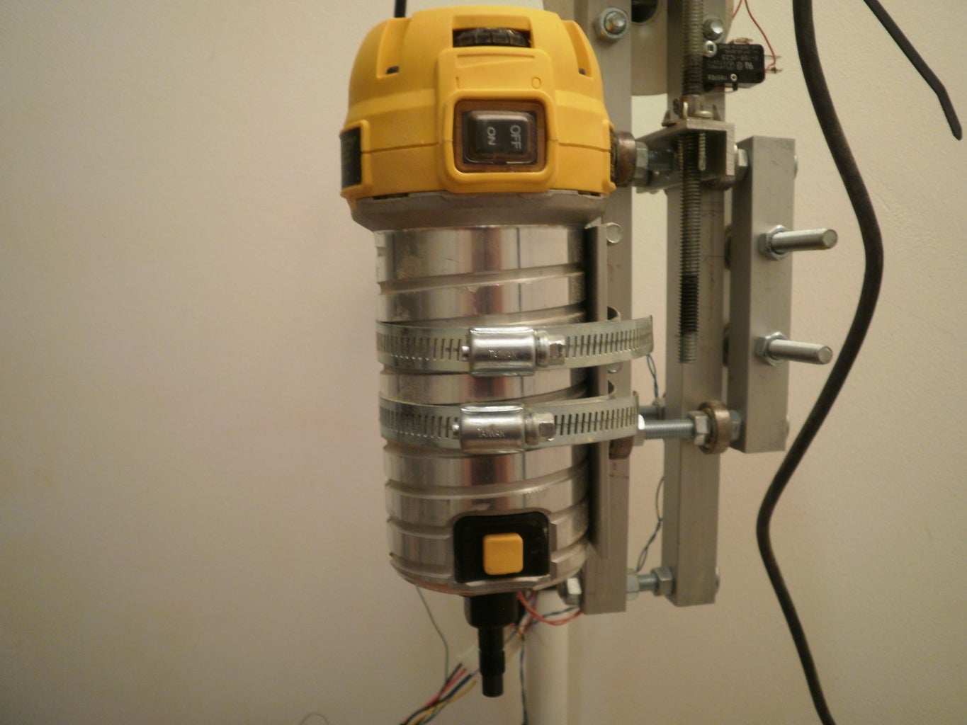
Step 6: Router (Spindle)


There have been two types of spindles I have tried:
2013: Dremel 4200
2012: DeWalt DWP 611 handheld router. It is variable speed and is rated at 1.25 HP.
The spindle is attached to the Z Axis using screw-drive hose clamps. The spindle is wedged in between 4 carriage bolts that are use to fasten the bearings to the bearing blocks.
Step 7: Lead Nuts


The "lead nuts" are made of 5/16" t-nuts with holes drilled through them. The t-nut is then screwed onto a piece of 1/8" x 0.75" aluminum angle. These were then fastened to the bearing assemblies.
There is barely any backlash with these t nuts. I don't have a dial indicator to find out exactly how much.
Step 8: Lead Screws and Screw Supports


The lead screws are cheap 5/16" zinc-coated steel thread rod. With these, the most consistent feedrate I can use is about 380 mm/min or about 15 in/min. This is when not using the most optimal setting for the motors.
The screw supports are very important. Looking at the couplings, they look essentially like springs to allow any sort of misalignment of the lead screw. This causes a problem because a force along the direction of any axis causes unwanted play.
With these screw supports installed on all axis, there is absolutely no play. The supports allow all of the torque from the motor to be transferred directly to the the lead nut.
The bearings are clamped from both sides using nuts. The bearings are fixed to the frame using 1/2" conduit clamps. With a bit of filing, they fit over the bearings perfectly.
Step 9: Couplings


I purchased the couplings on eBay as well for about $4 each from Hong Kong.
One end has a 1/4" (6.35 mm) bore for the stepper motor and the other end has an 8 mm bore for the lead screw.
Again, 5/16" is slightly less than 8 mm so in this case I filled the lead screw threads with epoxy and sanded it down to fit into the coupling.
If regular, cheap thread rod is your choice for the lead screw, I highly recommend the coupling in the main photo versus the one in the second photo. The one in the second picture requires a smooth shaft because the screws are tightened dig into the shaft in order to provide the clamping force. When I realized that it wouldn't work with a fully threaded rod I bought ones that clamp the rod circumferentially and clamp it from all sides.
Step 10: Motor Mounts


All the motors are connected to cross bars using only two of the 4 motor mounting holes. Two bolts seems to suffice to keep them secure.
Step 11: Cutting Platform
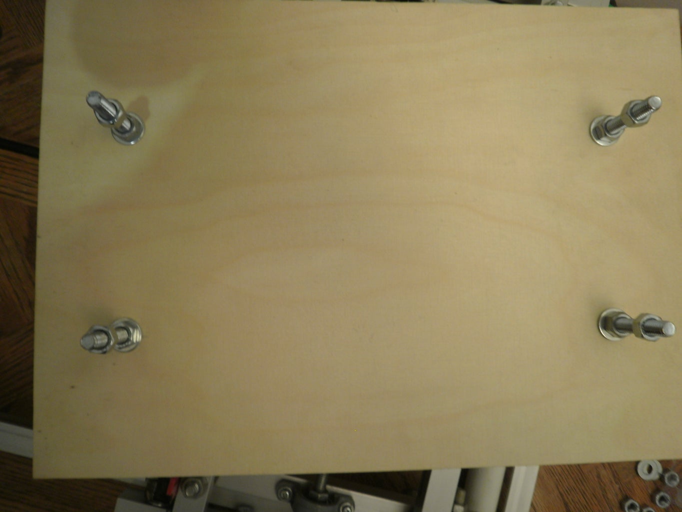


The cutting bed/platform is piece of Russian birch plywood. It is the highest quality of wood I found at the local Home Depot. It cost me $20 for a 2' x 4' sheet. The thickness is 11.5 mm.
As I said earlier, the cutting area is about 12" x 8" x 3". However, I cut the platform to a size of 14" x 10". The reason for this is that I can use extra length and width for clamping area. This is the advantage of this sort of design: it is easier to fix stock to the cutting bed.
The counter-bored carriage bolts are intentionally a little long which allow me to adjust the table to be square to the cutting bit.
Step 12: Limit Switches


Limit switches are your best friend when it comes to CNC (in my opinion). During some tests, before I installed my switches, I jogged the z axis too high and I almost stripped apart my Z axis coupling. The coupling got extended a little but it was no biggy.
I have installed a limit switch at each end of the X and Y axis. I also installed one at the top of the Z axis.
I wired these up all in series so if one of them is triggered. the machine automatically ceases.
Step 13: Cable Management


There are a lot of wires so it is important to keep them from getting in the way. The wires that come with stepper motors are very short. I extended mine with the wires from an old computer power supply. I also sleeved the wires using some custom computer mod sleeving. They keep things nice and tidy. Finally zip ties were used to tie wires to the frame
I used some molex connectors so I can disconnect the machine from the driver board easily.
The aluminum tubing allows me to route wires through, tucked away from harm.
Step 14: Electronics/Driver Board


I used a cheap TB6560 driver board that I bought on eBay. These things are really CHEAP. I actually went through 3 different Toshiba TB6560 controllers. 1 was faulty out of the box, 1 became faulty after some use and one fried. The controllers are easy to replace if you're comfortable with soldering. The replacements have held on for quite a bit but I suggest buying a higher quality driver.
I installed the driver board and power supply into my computer case. The driver board is screwed into a piece of clear acrylic and the acrylic is screwed to the expansion slots on the case. I replaced the stock fan of the driver board with one that came off of an old graphics card cooler.
Sorry for the blurry photos.
Step 15: Testing
Videos have been removed.
Step 16: Updates

February 17, 2013: I have made a separate instructable on a vacuum hose clamp I have designed for dust collection that also deflects the router exhaust air sideways. This ensures most of the dust isn't kicked around the shop.

Finalist in the
Hurricane Lasers Contest


