

Introduction: DIY Amp / Watt Hour Volt Meter - Arduino


Major corrections and additions made 9/9/2014
See the new and improved 2015 version at http://www.green-trust.org/jmc
For my off-grid Ham Radio and Solar projects, I needed a way to measure volts, amps, watts, amp hours and watt hours. There's a couple of commercial products that can do this, but not with the flexibility I wanted. I designed a Arduino micro-controller based solution that is very extensible. Right now it monitors the above values of attached gear, and I'm thinking about adding web monitoring and a sd card for data collection. Well, let's get started.
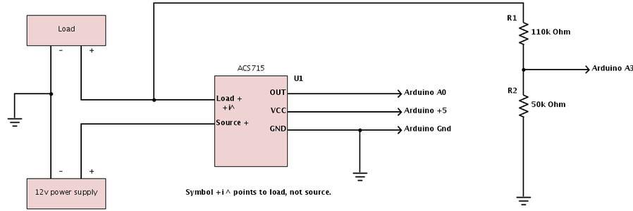
Step 1: Voltage Divider

UPDATE 9/9/2014 !
The Arduino can accept up to 5v on a analog input. Our voltage can range as high as 20vdc in certain situations (open circuit pv voltage), so we designed a voltage divider that would provide 5v at 20v battery voltage, and less at various lower voltages. See http://en.wikipedia.org/wiki/Voltage_divider for more information on Voltage Dividers.
First we visit our friendly Voltage Divider Calculator. I input 20v as the input, 5v as the output, and 10k for R2 (experiment with <10k resistors till you get a likely pair). This calculates a R1 of 30K.
R1 = 30k Ohms
R2 = 10k Ohms
Vout = (R2 / (R1 + R2)) * Vin
Vout = (10000 / (30000 + 10000)) * 20v
Vout = (10000 / 40000) * 20v
Vout = .25 * 20v
Vout = 5v
Ratio = Vin / Vout
Ratio = 4
Because the Arduino has a 10-bit ADC, it outputs 0-1023 (1024 steps) for a 0-5v input. That's 0.00488v / step.
With a Voltage Divider with R1 = 30k Ohm and R2 = 10k Ohm, A 12v battery would calculate as follows:
12v / Ratio = 3v on the A4 pin.
3v / .00488 = 615 (ADC Reading - round up)
so A4 pin Voltage = .00488 * ADC reading (615 in this case), or 3.00 volts.
Then battery voltage = A4 pin voltage * Ratio (3 * 4 = 12)
The code to read that value is as follows:
ADCVal = analogRead(batMonPin); // read the voltage on the divider on pin A4
pinVoltage = ADCVal * 0.00488; // Calculate the voltage on the A/D pin
// A reading of 1 for the A/D = 0.00488mV
// if we multiply the A/D reading by 0.00488 then
// we get the voltage on the pin.
batteryVoltage = pinVoltage * Ratio; // Use the Ratio calculated for the voltage divider
// to calculate the battery voltage, Ratio = Vin / Vout
More details at http://arduinotronics.blogspot.com/2012/04/voltage-monitor.html
UPDATE:
Improved voltage reading circuit and sketch at AC Volt Meter (works with DC as well). Rock solid voltage measurement, and very accurate.
Step 2: Current Monitoring

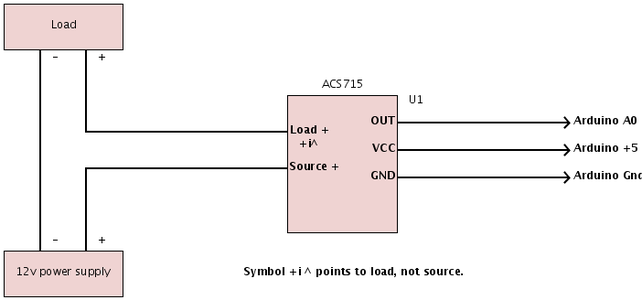
The next step is to track the current being consumed by a load, or produced by a source. We are using a ACS715 Hall Effect sensor to track the current being passed.
Update! ACS714 Bidirectional current sensor now being deployed. This will enable a battery "gas gauge" for "AH IN - AH OUT = AMP Remaining" type monitoring.http://www.hacktronics.com/Sensors/Current-Sensor-30-to-30-Amp/flypage.tpl.html
Update! ACS712 5amp sensor project at
http://arduinotronics.blogspot.com/2014/01/volt-amp-watt-hour-meter-shield.html
// read the analog in value:
sensorValue = analogRead(analogInPin);
// convert to milli amps
outputValue = (((long)sensorValue * 5000 / 1024) - 500 ) * 1000 / 133;
amps = (float) outputValue / 1000;
More details at http://arduinotronics.blogspot.com/2012/04/monitoring-power-consumption-with.html
Step 3: Math Alert!

To calculate watt (volts * amps), amp hours (amps * hours), and watt hours (watts * hours) requires tracking the time component, and performing a bit of math:
float watts = amps * batteryVoltage;
sample = sample + 1;
msec = millis();
time = (float) msec / 1000.0;
totalCharge = totalCharge + amps;
averageAmps = totalCharge / sample;
ampSeconds = averageAmps*time;
ampHours = ampSeconds/3600;
wattHours = batteryVoltage * ampHours;
Step 4: Serial Output

We can now output the results of the calculations to the serial port using the following code:
Serial.print("Volts = " );
Serial.print(batteryVoltage);
Serial.print("\t Current (amps) = ");
Serial.print(amps);
Serial.print("\t Power (Watts) = ");
Serial.print(watts);
Serial.print("\t Time (hours) = ");
Serial.print(time/3600);
Serial.print("\t Amp Hours (ah) = ");
Serial.print(ampHours);
Serial.print("\t Watt Hours (wh) = ");
Serial.println(wattHours);
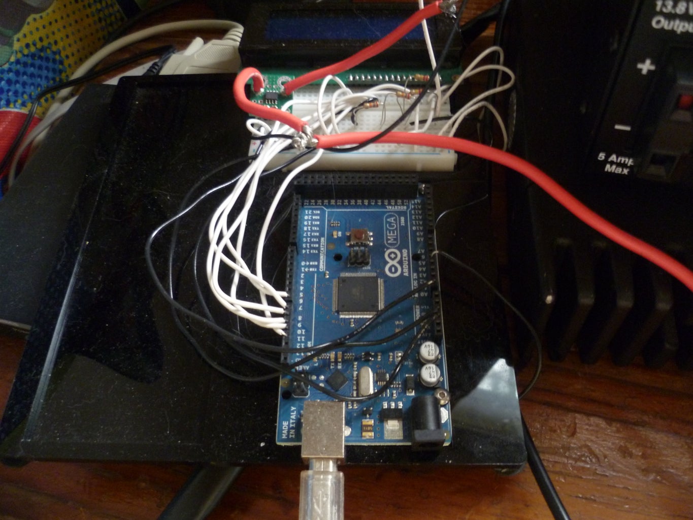
Step 5: LCD Display


Keeping a computer connected all the time is inconvenient, so I added a 4 line lcd display to the project.
lcd.setCursor(0,0);
lcd.print(batteryVoltage);
lcd.print(" V ");
lcd.print(amps);
lcd.print(" A ");
lcd.setCursor(0,1);
lcd.print(watts);
lcd.print(" W ");
lcd.print(time/3600);
lcd.print(" H ");
lcd.setCursor(0,2);
lcd.print(ampHours);
lcd.print(" Ah ");
lcd.print(wattHours);
lcd.print(" Wh ");
Step 6: Source Code
All the code, schematics, and photo's along with discussion is available at http://tech.groups.yahoo.com/group/arduinohome/files/volt%20amp%20watt%20hour%20meter/ and http://forum.pololu.com/viewtopic.php?f=3&t=5415
#include
/* This sketch describes how to connect a ACS715 Current Sense Carrier
(http://www.pololu.com/catalog/product/1186) to the Arduino,
and read current flowing through the sensor.
*/
LiquidCrystal lcd(7, 8, 9, 10, 11, 12);
/*
Vcc on carrier board to Arduino +5v
GND on carrier board to Arduino GND
OUT on carrier board to Arduino A0
Insert the power lugs into the loads positive lead circuit,
arrow on carrier board points to load, other lug connects to
power supply positive
Voltage Divider
9k Ohm from + to A4
3k Ohm from A4 to Gnd
*/
int Vin = 20;
int Vout = 5;
int ratio = Vin / Vout; // Calculated from Vin / Vout
int batMonPin = A4; // input pin for the voltage divider
int ADCVal = 0; // variable for the A/D value
float pinVoltage = 0; // variable to hold the calculated voltage
float batteryVoltage = 0;
int analogInPin = A0; // Analog input pin that the carrier board OUT is connected to
int sensorValue = 0; // value read from the carrier board
int outputValue = 0; // output in milliamps
unsigned long msec = 0;
float time = 0.0;
int sample = 0;
float totalCharge = 0.0;
float averageAmps = 0.0;
float ampSeconds = 0.0;
float ampHours = 0.0;
float wattHours = 0.0;
float amps = 0.0;
int R1 = 9000; // Resistance of R1 in ohms
int R2 = 3000; // Resistance of R2 in ohms
int ratio = 0; // Calculated from Vin / Vout
void setup() {
// initialize serial communications at 9600 bps:
Serial.begin(9600);
lcd.begin(20, 4);
}
void loop() {
int sampleADCVal = 0;
int avgADCVal = 0;
int sampleAmpVal = 0;
int avgSAV = 0;
for (int x = 0; x < 10; x++){ // run through loop 10x
// read the analog in value:
sensorValue = analogRead(analogInPin);
sampleAmpVal = sampleAmpVal + sensorValue; // add samples together
ADCVal = analogRead(batMonPin); // read the voltage on the divider
sampleADCVal = sampleADCVal + ADCVal; // add samples together
delay (10); // let ADC settle before next sample
}
avgSAV = sampleAmpVal / 10;
// convert to milli amps
outputValue = (((long)avgSAV * 5000 / 1024) - 500 ) * 1000 / 133;
/* sensor outputs about 100 at rest.
Analog read produces a value of 0-1023, equating to 0v to 5v.
"((long)sensorValue * 5000 / 1024)" is the voltage on the sensor's output in millivolts.
There's a 500mv offset to subtract.
The unit produces 133mv per amp of current, so
divide by 0.133 to convert mv to ma
*/
avgADCVal = sampleADCVal / 10; //divide by 10 (number of samples) to get a steady reading
pinVoltage = avgBVal * .00488; // Calculate the voltage on the A/D pin
/* A reading of 1 for the A/D = 0.0048mV
if we multiply the A/D reading by 0.00488 then
we get the voltage on the pin.
Also, depending on wiring and
where voltage is being read, under
heavy loads voltage displayed can be
well under voltage at supply. monitor
at load or supply and decide.
*/
batteryVoltage = pinVoltage * ratio; // Use the ratio calculated for the voltage divider
// to calculate the battery voltage
amps = (float) outputValue / 1000;
float watts = amps * batteryVoltage;
Serial.print("Volts = " );
Serial.print(batteryVoltage);
Serial.print("\t Current (amps) = ");
Serial.print(amps);
Serial.print("\t Power (Watts) = ");
Serial.print(watts);
sample = sample + 1;
msec = millis();
time = (float) msec / 1000.0;
totalCharge = totalCharge + amps;
averageAmps = totalCharge / sample;
ampSeconds = averageAmps*time;
ampHours = ampSeconds/3600;
wattHours = batteryVoltage * ampHours;
Serial.print("\t Time (hours) = ");
Serial.print(time/3600);
Serial.print("\t Amp Hours (ah) = ");
Serial.print(ampHours);
Serial.print("\t Watt Hours (wh) = ");
Serial.println(wattHours);
lcd.setCursor(0,0);
lcd.print(batteryVoltage);
lcd.print(" V ");
lcd.print(amps);
lcd.print(" A ");
lcd.setCursor(0,1);
lcd.print(watts);
lcd.print(" W ");
lcd.print(time/3600);
lcd.print(" H ");
lcd.setCursor(0,2);
lcd.print(ampHours);
lcd.print(" Ah ");
lcd.print(wattHours);
lcd.print(" Wh ");
lcd.setCursor(0,3);
lcd.print(ratio, 5);
lcd.print(" ");
lcd.print(avgBVal);
// wait 10 milliseconds before the next loop
// for the analog-to-digital converter to settle
// after the last reading:
delay(10);
}

Step 7: Future Expansion

Some of my ideas for expanding this project were along the lines of communications, like wifi or ethernet, with onboard webserver or attaching to Pachube / Cosm / Xively (https://xively.com/), a sd card for data logging, and today I had the idea of adding a low voltage disconnect to protect the battery from excessive discharge. I also designed a hybrid relay, which eliminates heating of the MOSFET Switch, and arcing of the relay contacts. I'll develop the code for this item shortly.
The hybrid relay enables spinoffs like dump load controllers for wind turbines, and load shedding for multi stage power downs or controlled power usage based on battery voltage or load priority.
Step 8: Protoboard
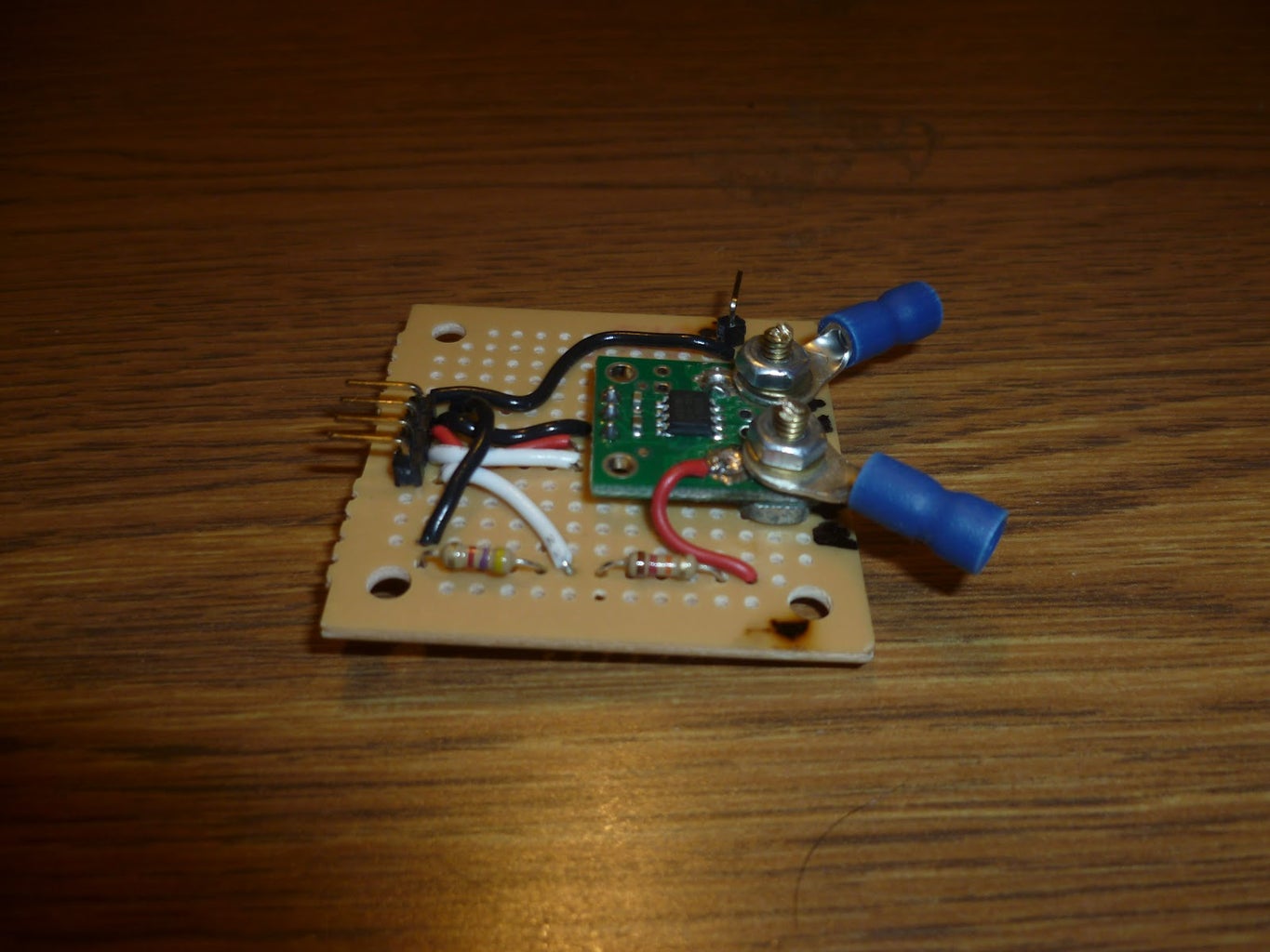

We have moved the current and voltage sensor off the solderless breadboard, and onto a Radio Shack proto board. This is more sturdy and "permanent".
Step 9: Web Based Interface With Database Back End

Currently working on a new web based front end, and a database back end. This will allow you to monitor your system remotely with a computer or smartphone, and see historical usage data. Stay tuned, coming very soon!

Participated in the
Make It Real Challenge


