

Introduction: DIY Android Remote Control Car With Arduino


This is a step by step guide on how to build an Android phone or tablet controlled paper Car. You can modify it to build any other type of vehicle that you like.
Steps include guide on:
1. Building up the hardware of the car
2. Programming the Arduino UNO as the main engine ( controller) of the car from the sample code provided.
3. Writing an app with MIT app inventor and install it to Android phone or Tablet as the remote control unit, with sample provided.
Step 1: Get the Materials and Tools Ready

Before we start anything, we need to prepare materials and tools for the project.
Materials and Tools needed are listed as below together with link to where to get the item:
1. Cube Servos x2
2. rero Cube Joint x2
(soon in Cytron production)
3. rero Slim Wheels x4
4. rero Inter Connect
5. rero Rotatable Connect
6. rero Opener
7. Arduino UNO or Cytron UNO or Cytron UNO Special Edition
8. Cytron XBee Shield with Cytron BlueBee Module.
9. Cytron G15 Shield
10. Battery Pack (any battery pack with voltage more than 7V) , Battery Holder.
11. Cytron BlueBee.
12. Paper Box
13. Scissor
14. Cutter
15. Double Sided Tape
16. Paper glue
17. Plastic Card Board
Step 2: Get Ready the Car Base


This Step shows the making of the car base to mount the Cube servo and Arduino board and shields. The car base is made from a plastic card board which you can easily get from stationary shop.
Follow simple steps below:
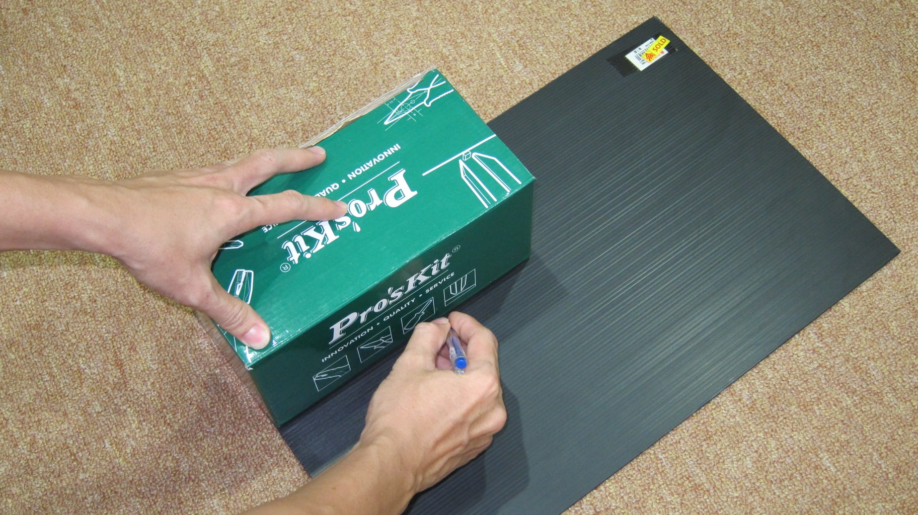
1. In order to match the frame of the car which is made from a paper box later,trace the size of the box onto the plastic card board. My paper box dimension is 23.5cm x12cm x12cm (L x W x H).
2. Cut out the plastic card board following the traces that we made using a cutter with the help of a ruler. Make sure to cut a little smaller than what we had traced from the paper box just now so that the cut out can fit into the paper box. (see last picture, which the card board fit well into the paper box.
Step 3: Prepare the Vehicle Wheels


The car wheels will be made from the Cube Servo and Cube Joint attached with Rero's Wheel. We will create two set of wheels, ie. the driving back wheel with Cube Servo, and free running front wheel with Cube Joint and Rotatable Connect.
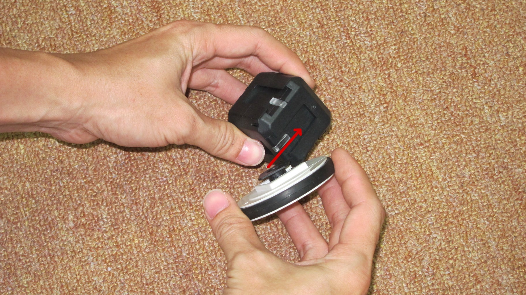
Back Wheel with Cube Servo:
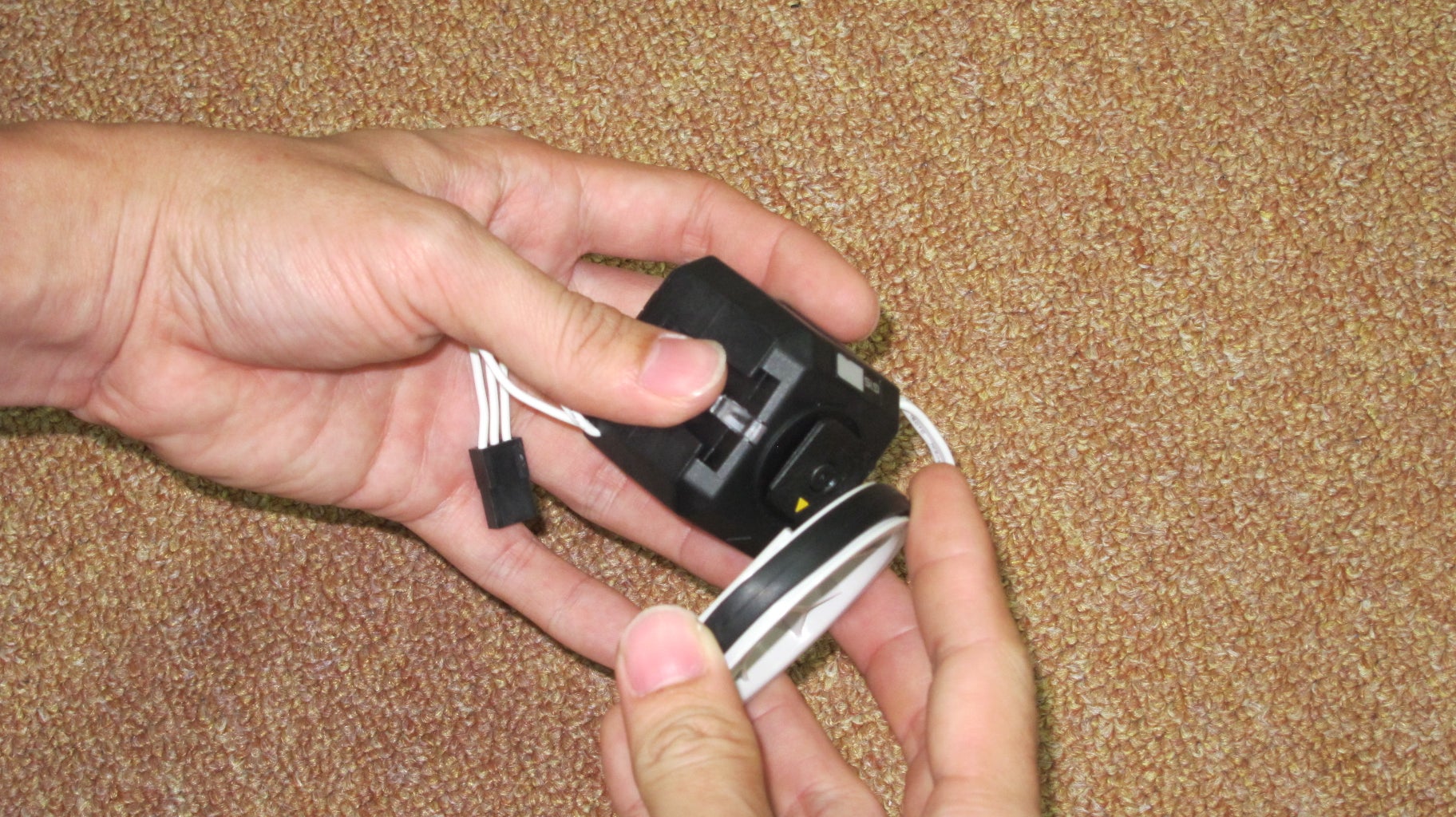
1. Slide the Rero Wheel onto the Cube Servo Output Connect (Output Shaft). Do the same for both Cube Servo.
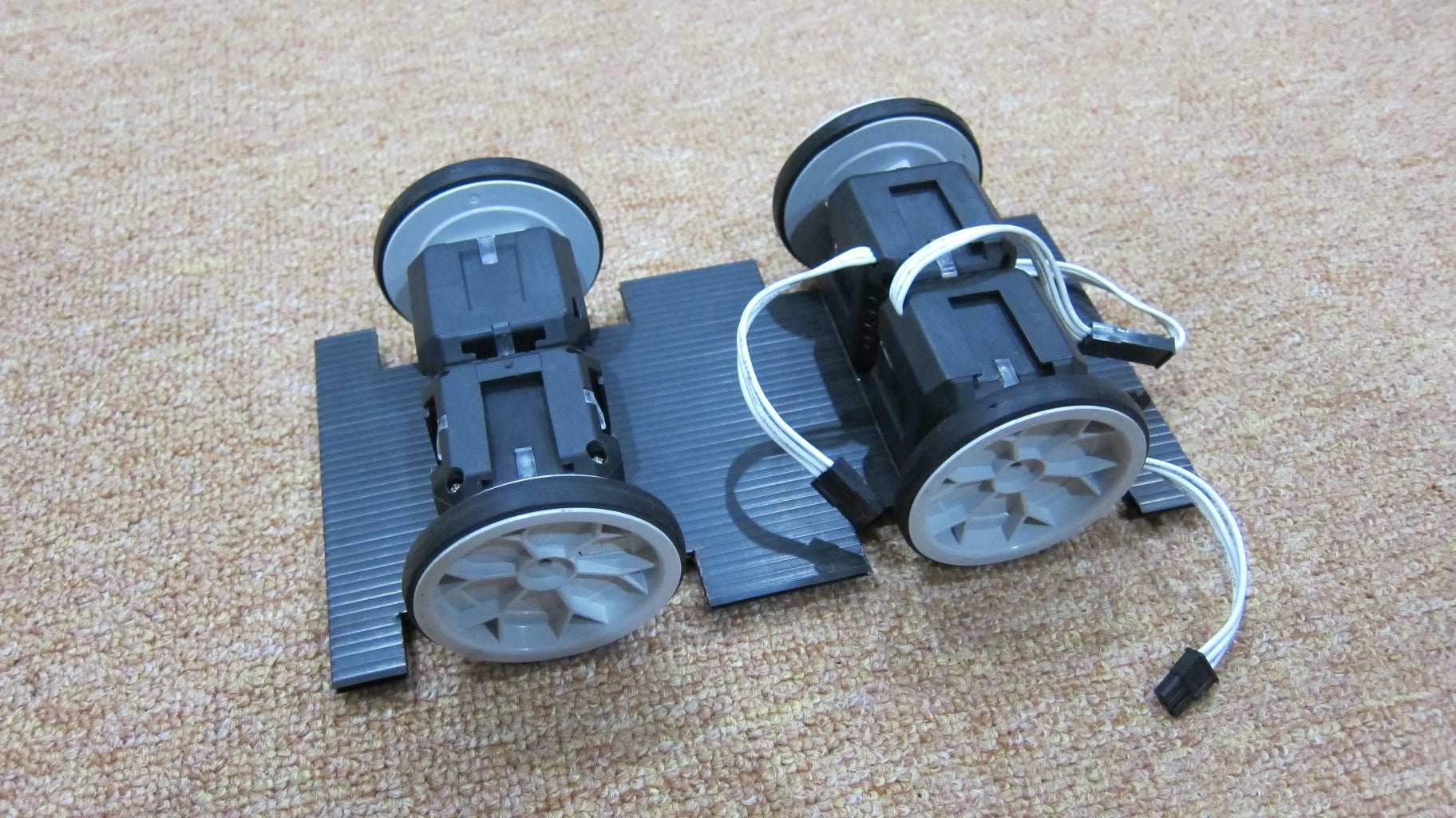
2. Slide an Inter Connect into opposite surface of Cube Servo's output connect. Slide to connect both Cube Servo together back to back. (See picture below).
3.
Front Wheel with Cube Joint:
1. Slide a rotatable connect to a Rero Wheel and do the same for the other wheel.
2. Slide the Rero Wheel attached with rotatable connect onto a Cube Joint. Do the same for the other wheel. This will create two free running wheel on the Cube Joint.
3. Slide an Inter Connect onto a cube joint on the surface which is opposite of the wheel, and connect both Cube Joint together with the Inter Connect.
Step 4: Attach the Wheels to the Base


In this step, we will make several cut out on the Plastic Card Board to give space for the wheels.
1. Position the wheel to a suitable spacing on the card board.
2. make markings on the side of the card board for both of the wheels (see picture below) .
3. Draw straight line across the card board on the markings that was made just now. For my case, it is around 5.5cm from each end of base. This lines are the middle lines where the two set of the wheels will be place.
4. Make cutting on the card board to fit the wheel (refer the fourth picture ). In my case, depth 1.8cm into card board for each of wheels and width 7.5cm
5. Cube servo width is 4.5cm. Draw guideline to place the Cube Servo properly. Put on double side tape to the area that will be covered by Cube Servo with wheel. (refer picture). Press double sided tape firmly to the base.
6. Peel of double sided tape cover to reveal the sticky surface and stick the Cube Servo wheel assembly to the base (refer last two pictures.
Step 5: Setting Up for Arduino and Shields


We will setup the Arduino UNO, Cytron G15 Shield and Cytron XBee Shield as the controller of the car in this step.
1. Connect the two Cube servo together, the male connector to the female connector (Cube servo are connected serially i.e. daisy chained).
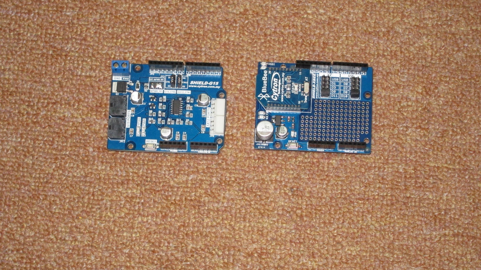
2. Setup the Cytron G15 Shield: set the jumper on board to select D3 and D2.
3. Setup the Cytron XBee Shield: set the jumper on board to select D11 and D10.
4.Stack the Cytron G15 Shield onto Arduino UNO then Cytron XBee Shield onto Cytron G15 Shield.
5. Fix the position of Arduino Stack and battery pack to the base using double sided tape on the other side of the base (opposite the surface where Cube Servo were sticked). Please put more weight to the Cube Servo side (refer the fourth picture where both Arduino stack and battery pack are placed near to the Cube Servo side).
6. Program the Arduino UNO ( download the source code below, compile and download the Arduino UNO).
7. Plug the the left over male connector of Cube Servo to the Cytron G15 Shield.
Attachments

Step 6: Create the Android App With MIT App Inventor


This step is to create the Android App and download the App to the phone to use the phone as the remote controller.
1. Go to the MIT App Inventor 2 page.
2. Click Create to start creating the app. Login using Google Account.
3. Click Project -> Import to import the project from the attachment below ( extract the RemoteWithAcc.zip file to get RemoteWithAcc.aia before import)
4. After Import was successful, click to open the project.
5. If you wish to try the app, you can click Connect on the MIT App Inventor Page and select one of the options available according to your preference, I tested it with AI Companion which requires the installation of MIT APP Inventor 2 app from Play Store on the phone.
6. If you wish to install the app directly to your phone, you can click on Build App (save to my computer) then download the app to your phone and install it.
Attachments
Step 7: Test Drive the Car
We will test drive the car in this step:
1. Upon successful installation of the app. Turn on the bluetooth on the phone manually. Pair the bluetooth of the phone with the BlueBee on the car. You will need to power on the the Arduino stack by now. (make sure the BlueBee is in transparent mode -Trans before power on). The pass key required for the pairing is 1234.
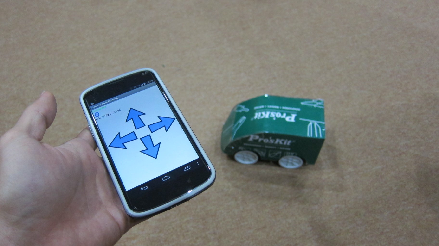
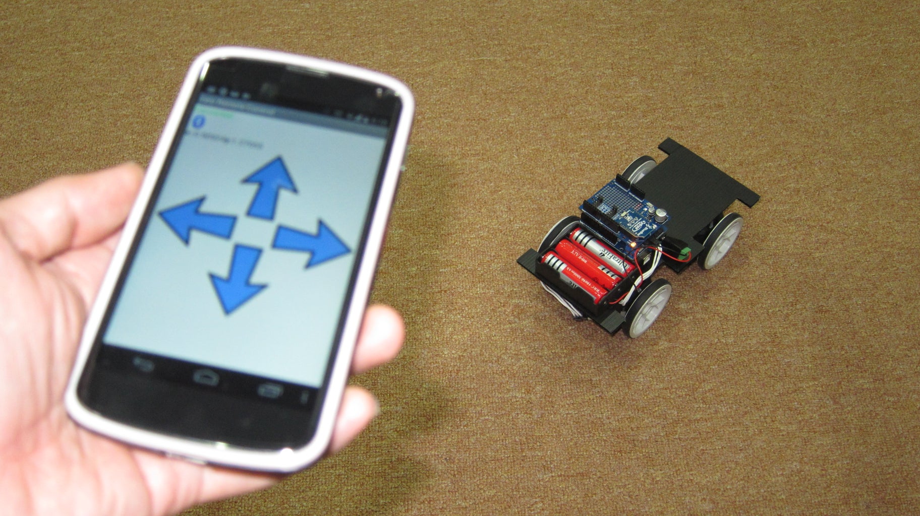
2. Open the App and press the bluetooth icon on the app, and select BlueBee to connect it. The label above the bluetooth icon will show Connected in green color if the connection was successful.
3. Now, test drive the car by tilting the phone to front, back and side to move the car forward, backward and turn left and right. The app use the accelerometer on phone to as the control.
Step 8: Car Body With the Paper Box


If you are satisfied with the car without body, then your can skip the following steps. Following step will shows the making of the car body.
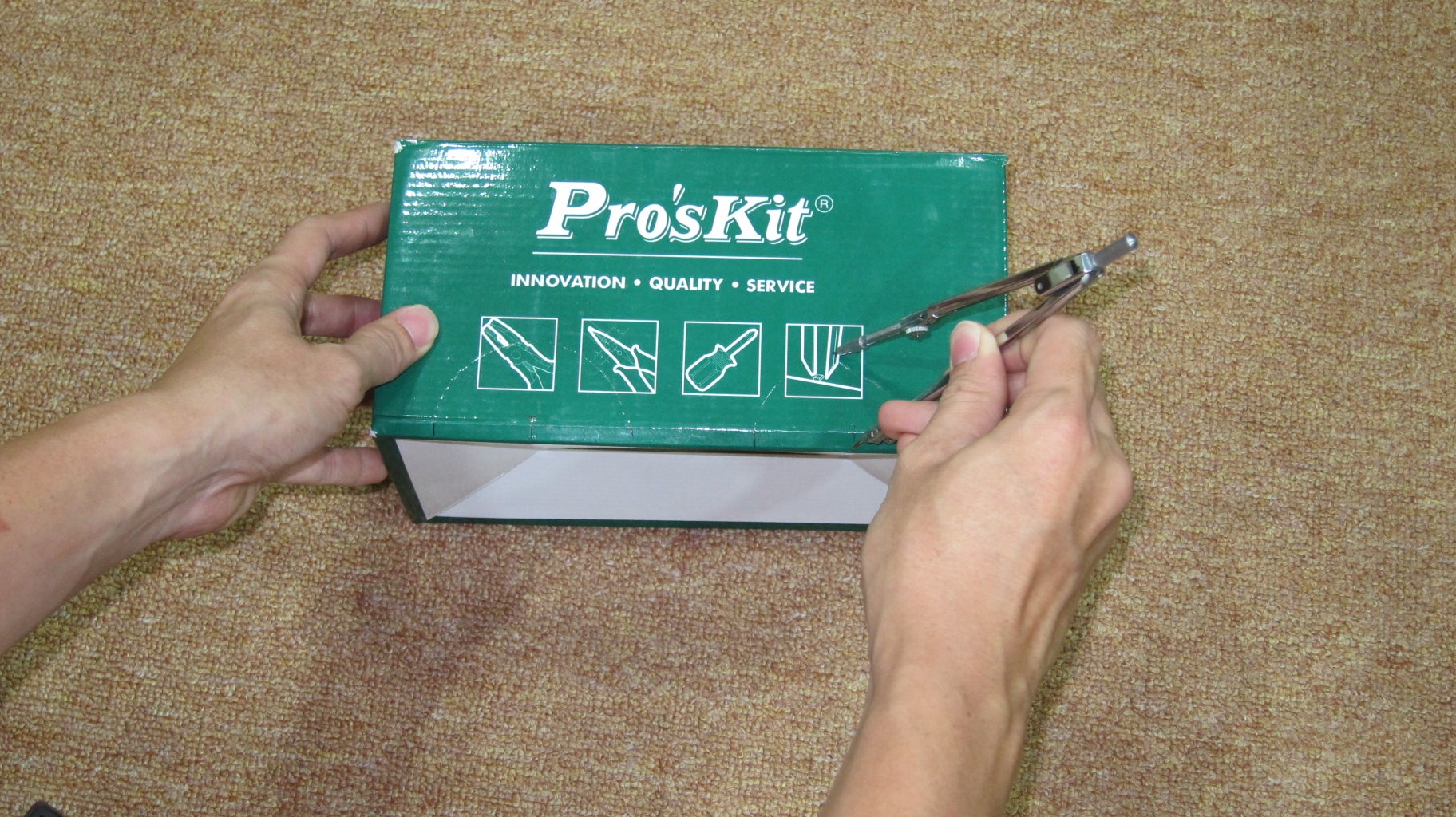
1.Mark the Wheel center position on the box's sides. We will cut out semi-circle to fit for the wheel. The wheel center is around 5.5 cm from the ends of box for my case and adding some offset for the paper thickness (in my case 2mm) for each end.
2. Use a compass to draw circles, set the center of semi-circle to the markings made just now.
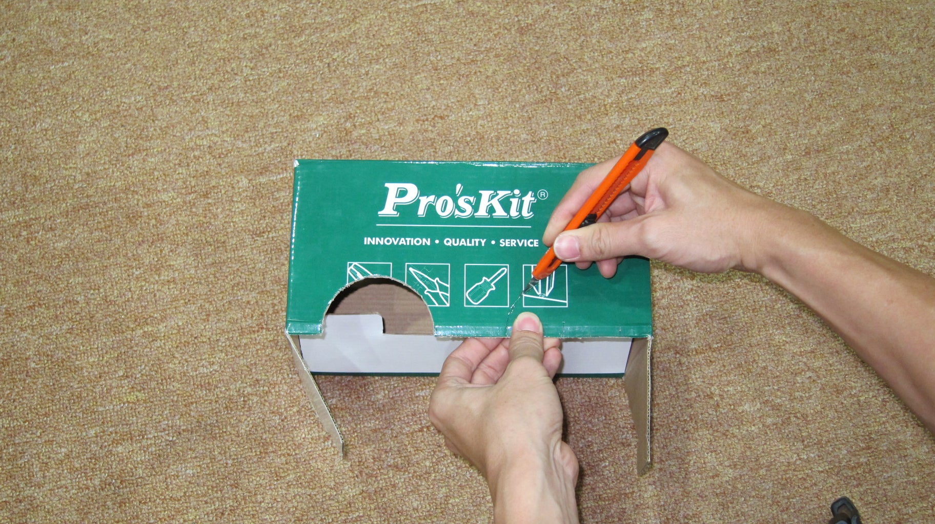
3. Cut out the semi-circle together with the bottom part of the box.
4. Try to fit the base with wheel into the box (refer last picture). Make necessary modifications to the cutting to fit the wheels well.
5. Lastly you can make some decorations and cuttings to the box to make it more like a car instead of cuboid box.
6. I put some double sided tapes inside the car body to prevent the car base going to far into the body and wheels touch the body.
Step 9: Ready to Go
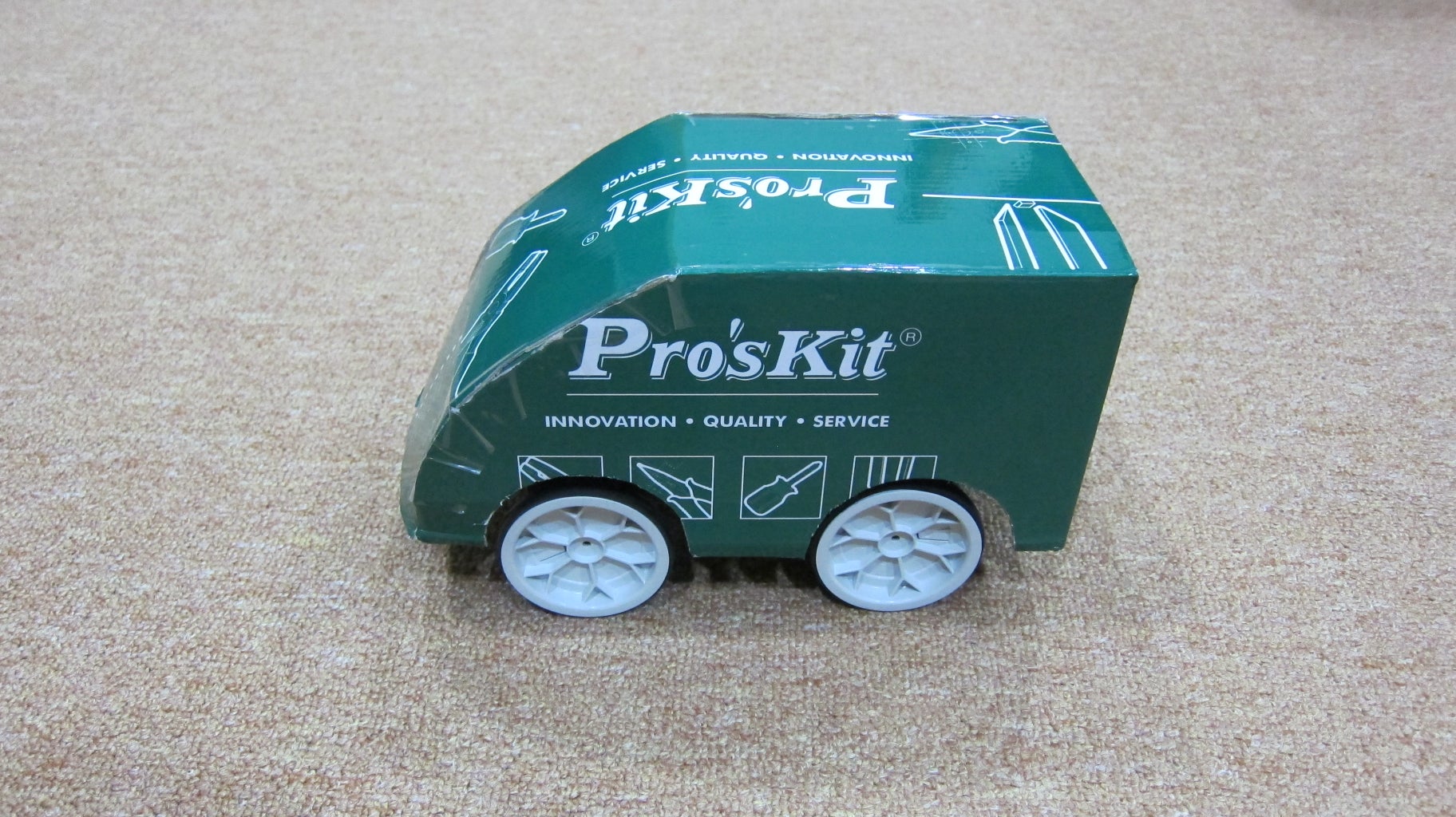
Lastly put on the car body and the car is ready to go!


