

Introduction: DIY Arduino Nebulophone Synth


I looked at the schematic and realized that Dr. Bleep had left plenty of things missing such as where did the stylus go and, where were the keypads and so I emailed him and after a long string of emails everything was cleared up.
I don't have that many photos but the photos I did take explain a lot.
Here is a video of the original updated one:
Step 1: The Bits and Pieces Needed
10cm of copper tape (You should get 11cm in case of any trouble...Really any measurement will work; you just need to make it fit your board)
1 alligator clip
1 SPST/SPDT slide switch (Any type of switch that can move from one position to another until pused again work (Toggle, Rocker, etc.) It doesn't matter whether it is SPST or SPDT the second connection is nothing.)
2 Pushbuttons (Tactile works nicely.)
1 5mm LED (Really any size will work. This is the Arpeggio LED)
1 LED and Photocell assembly (I got mine from here but I didn't realize that the same website had this which is much cheaper although untested. You could also make your own by bending an LED over to a photocell that can range from 10k to 200k. and then covering it with some black tubing. I'm not sure the one I had is exactly 10k to 200k but it worked.)
1 speaker and amplifier
1 Rail to Rail Op-Amp (the article said tlc2262 but I improvised with tlc2272 and it works fine. IT MUST BE A RAIL TO RAIL OP-AMP)
1 row of male headers
1 DoAnything Shield (Really it is only an adapter...you don't have to use one.)
1 Piece of Large PerfBoard (This or this SHOULD work.)
3 0.1uF Capacitors
1 220uF Capacitor
1 8 pin IC Socket
1 Audio Jack (For output. You should use the size that fits your speaker and amplifier)
1 Power Supply (For the Arduino, of course. (9v battery, USB Cable, Wall Wart, etc.))
1 IR LED (Use the clear side-firing type) (I didn't add this; I don't own any other Andromeda Space Rockers or Gieskes )
1 IR PhotoTransistor (See IR LED)
1 HUGE BUNDLE OF WIRE (You will need both solid and stranded wire.)
1 Arduino
Step 2: Program.

This is the step where you take your Arduino and Program it. The code was written by Dr. Bleep.
REMEMBER: This is a large sketch. If it takes longer than a millisecond to program it it is because it is so big.
If all goes well, then you should have a dim flicker from the built-in LED on Pin 13.
Save the code in your Arduino Sketchbook folder
UPDATE: IF THE CODE (NEBULOPHONE V11) DOES NOT WORK, THEN TRY NEBULOPHONE.ZIP

Step 3: Build.


This is the tougher part. I have less photos here so I am sorry but I will do my best to explain thoroughly.
The first picture is the circuit. Click on the "i" in the upper left hand corner to view the circuit better.
NOTE: I will assume you have found a way to bypass the fact that the distance between Digital Pin 7 and Digital Pin 8 is not the standard 0.1".
- Take your male headers. You will want to move them towards the shorter side. This will enable it to plug into the Arduino more easily.
- Solder them face down so that the long side protrudes below the board as in Picture Three and Four. The black holder should be above. Next, solder the headers down.
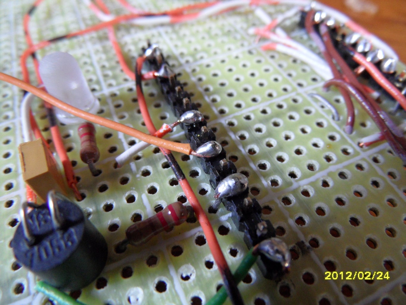
- You can now start placing components according to the schematic.You can follow my layout, Dr. Bleep's layout or your own layout.
- The way I soldered wires to connection was I took the wire and stripped the end and wrapped it around as in Picture 8. I then soldered it as in Picture 9.
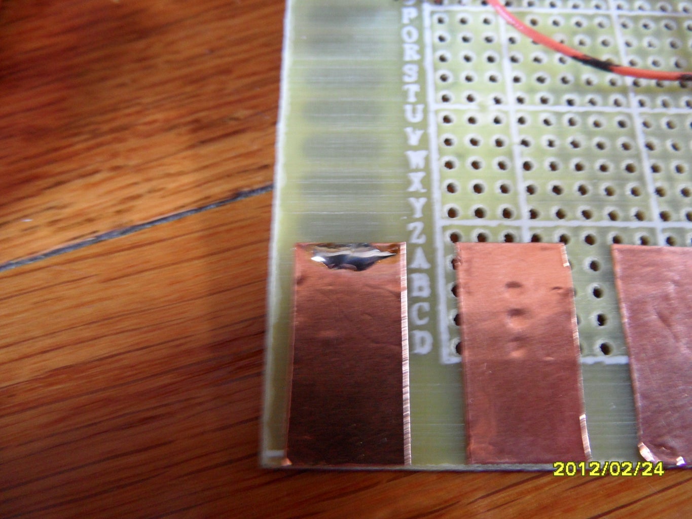
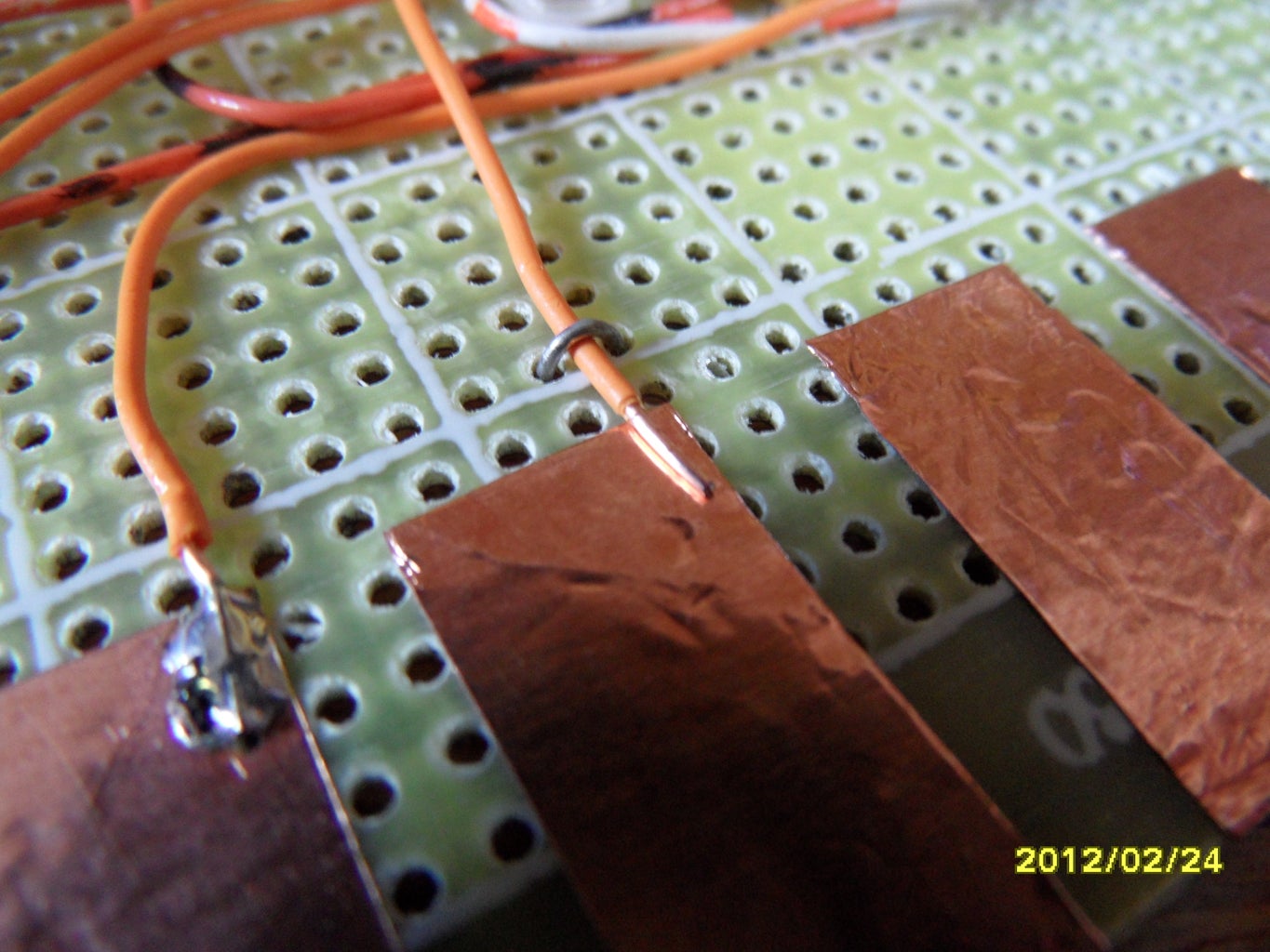
- Now comes the tedious part. Take your copper tape and with a small knife (X-acto) Score at an interval. Because I had 15 cm to use I had 1 cm pieces with 0.5cm in between each one. (Approximately.)
- Once scored I tediously did it again on the other side to make it look like Picture 9.
- Now, cut the copper tape into the individual keys.
- Next, tape it on and then tin the tops so that the wires can stick. Soldering to a length of copper is not easy. It takes a while before it heats up to a high enough temperature. An example is Picture 10. However after you tin or solder it, DO NOT TOUCH. IT IS VERY HOT.
- The schematic went through multiple revisions before it was working. I am assuming that you have placed all your components except for the stylus and keypads. The keypad pins on the Arduino's Digital Pins are, from left to right, lowest pitch to highest pitch, as follows: 9, 10, 12, 0, 2, 4, 5, 6, 7, 8. Solder each pin to each pad. I found that if you strap down each wire with a component lead while soldering it helps keep the wire down as in Picture 11. Afterwards, you can remove it and reuse it for the next one.
- Once those are all soldered, the stylus needs to be installed. Take your stranded wire and cut a good length. Then, solder it to the alligator clip as in Picture 12.
- Solder the other end to ground.
- Whatever components you did not solder yet solder in. That includes output wires or jack. I soldered my pots last because they were the tallest.
- Now, install the Op-Amp.
- Plug it into the Arduino board.
- You're done!
Step 4: Finished!

At last we have completed it!
Analog 5, unlike the schematic is the Arpeggio pot. Analog 4 is the LFO Pot. Analog 3 is the Waveform pot.
I hope you enjoyed this Instructable.
Leave a comment if you have any questions or comments.
Attachments


Participated in the
ShopBot Challenge

Participated in the
Make It Real Challenge

Participated in the
Arduino Challenge


