

Introduction: DIY Arduino Temperature Sensor


This instructable will show you how to build a temperature sensor compatible with Arduino boards, which can be used for different home projects. It shows also a simple application, in which the DIY sensor is used for making a simple Arduino based indoor thermometer.
The temperature sensor is based on the Maxim's chip DS600U+. It has ±0.5 °C accuracy. Can be supplied from 2.7V to 5.5V.
"The DS600 analog temperature sensor measures it own temperature and provides these measurements to the
user in the form of an output voltage, VOUT, that is proportional to degrees centigrade. The output voltage
characteristic is factory-calibrated for a typical output gain (ΔV/ΔT) of +6.45mV/°C and a DC offset (VOS) of 509mV.
Its operating temperature range is -40°C to +125°C, corresponding to an output voltage range of 251mV to
1315mV. (VOUT = Device Temperature (°C) x ΔV/ΔT + VOS)." - DS600U+ datasheet.
The temperature behavior of the chip can be seen on the picture.
The chip does not require any additional devices. I added only a filtering capacitor between the
power rails. The schematic and the board of the sensor are presented on the pictures. They are also available for download.
The only needed parts for the sensor:
1 x DS600U+ chip - Maxim Integrated
1 x 10uF SMD Tantalum capacitor - not obligatory
1 x 6 pin header
Attachments

Step 1:


To build the sensor, I have created a small PCB. For that purpose I have used the toner transfer method. How to do this is object of many instructables. I have soldered the chip, the capacitor and the pin header. On the fifth pin of the sensor I put a small plastic tube taken from cable insulation. It's purpose is the lead the sensor in the right position and to block its insertion in wrong female header holes. On the pictures can be seen the right way in which it must be placed. The sensor is projected in the way that it use the following Arduino pins : "5V","GNG","GND", _ , _ ,"A0". That means - its analog output voltage value is sampled by ADC0.
Step 2: The Hardware
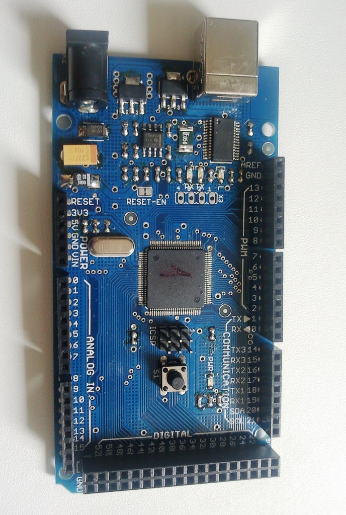


For the simple thermometer project based on the DIY temperature sensor I have used an Arduino MEGA board (also my DYI project).LCD shield is also needed. In my case the shield was also self-made. The LCD used is graphics 128x64 display with ST9720 chip.I bought it in ebay. The PCB for the LCD shield is also from ebay. I have soldered a female pin headers on the LCD, and pin headers on the protoshield - now I can simply insert the LCD module on the protoboard and it works fine and does not use any cables. If you do not have any LCD shield, of course the standard approach with breadbord can be used. For this project could be used also any character LCD ( for example 16x2), but I do not have one, and I went through the more complicated way :-).
Step 3: The Code


Now it is time to write the code. I tried to keep it as short and simple as possible. Because I use GLCD, I decided to base the implementation on the u8glib libraries. If you want to use character LCD, the standard LCD Arduino libraries should be used, and the code must be adjusted according them.
Here is the code:
/*
Thermometer based on Maxims DS600u+ chip
*/
#include "U8glib.h"
#include <math.h>
U8GLIB_ST7920_128X64_4X u8g(8, 9, 10, 11, 4, 5, 6, 7, 18, 17, 16); // 8Bit Com: D0..D7: 8,9,10,11,4,5,6,7 en=18, di=17,rw=16
void u8g_prepare(void) {
u8g.setFont(u8g_font_6x10);
u8g.setFontRefHeightExtendedText();
u8g.setDefaultForegroundColor();
u8g.setFontPosTop();
}
void setup(void) {
// flip screen, if required
//u8g.setRot180();
// assign default color value
if ( u8g.getMode() == U8G_MODE_R3G3B2 )
u8g.setColorIndex(255); // white
else if ( u8g.getMode() == U8G_MODE_GRAY2BIT )
u8g.setColorIndex(3); // max intensity
else if ( u8g.getMode() == U8G_MODE_BW )
u8g.setColorIndex(1); // pixel on
//u8g.setContrast(0x30);
pinMode(13, OUTPUT);
digitalWrite(13, HIGH);
u8g_prepare();
}
void draw(void) {
float supply = 4.91; // Here must be entered the measured supply voltage of the arduino board
//read the sensor output voltage
int reading = analogRead(0);
float v_out = (reading * supply)/1.024;
// show on the LCD the temperature
float temperature = (v_out - 509)/6.45 ;
char temp[5];
dtostrf(temperature,5,1,temp);
u8g.drawStr(4,24,"Temperature:");
u8g.drawStr(76,24,temp);
u8g.drawStr(108,24,"\260C");
}
void loop(void) {
// picture loop
u8g.firstPage();
do {
draw();
} while( u8g.nextPage() );
// rebuild the picture after some delay
delay(1000);
}
There are some tricky points in the code.
I have put them in bold.
1) Because the internal Atmega ADC uses as reference the supply voltage to measure analog voltage potential, which is not ratio metric to the supply voltage, but fixed by the sensor chip, if the supply voltage varies, an error can occur. Rough calculation says that 50mV supply variation can cause 1 degree temperature error. The solution to improve the accuracy is to measure the exact supply voltage on the Arduino board in the way it should be used - if you intend to use the Arduino thermometer supplied by the USB, you have to measure the board supply voltage for this case; and respectively, if you intend to use the thermometer as stand alone device supplied by AC/DC adapter - then, the supply voltage of the board+shield shall be measured in this condition. In my case the device is supplied by the USB, and I have measured 4.91V on the "5V" Arduino pins. So I put this value in the sketch.
2) It is nice that on the LCD you can see the degree " ° " symbol. The problem here is that the different displays have different ASCII tables, and what exactly is the octal number corresponding to the symbol is difficult to be said. There are two possible solutions :
A) to read the datasheet of the LCD module/ driver if there are given any ASCII tables
B) to write a sketch to display the whole ASCII table written in the LCD ROM, to see where the symbol appears and to calculate/see the decimal number corresponding to it. Further to convert this value to octal number and put in the sketch.
I have used the second approach...and in the easiest way :-) - there are "Examples" in the library u8glib. The program "GraphicsTest" prints both ASCII tables stored in the driver chip ROM. There i found that the needed symbol has the 260 octal equivalent number.
The guys, which want to implement this project on the Arduino Due, I would advice to insert in the code also the following line:
analogReadResolution(12);
in the setup procedure ,and then instead to divide on 1.024 to divide on 4.096. This will improve the ADC resolution and somehow also the thermometer accuracy.
Step 4:


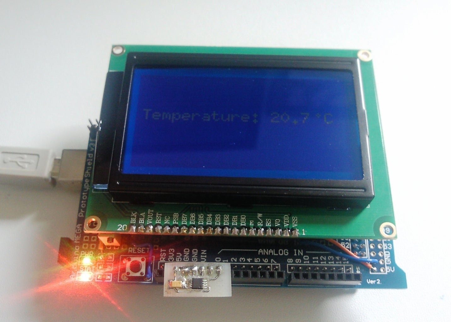
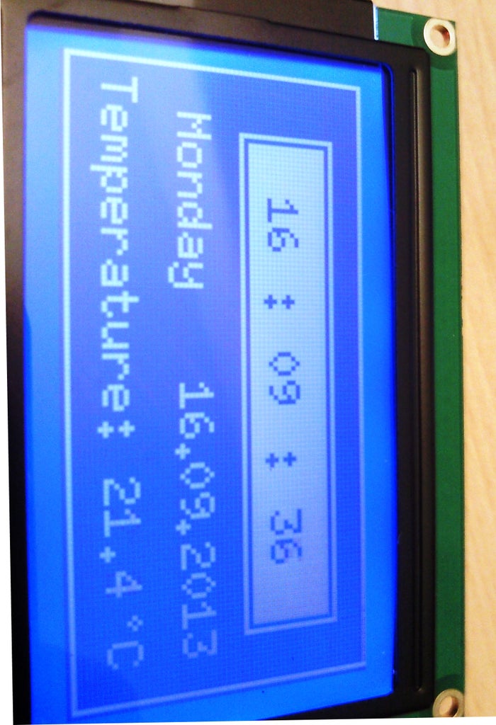
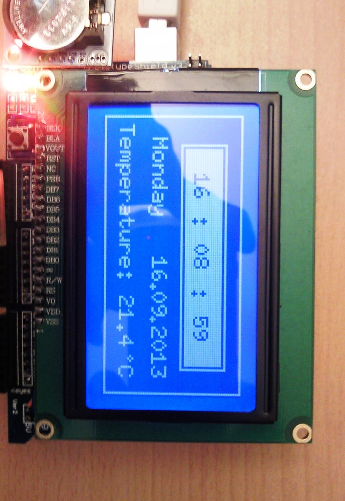
The whole device assembled, programmed and functioning:
P.S. The project continues...
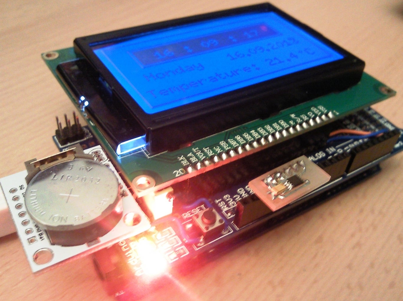
Step 5: Additional Works
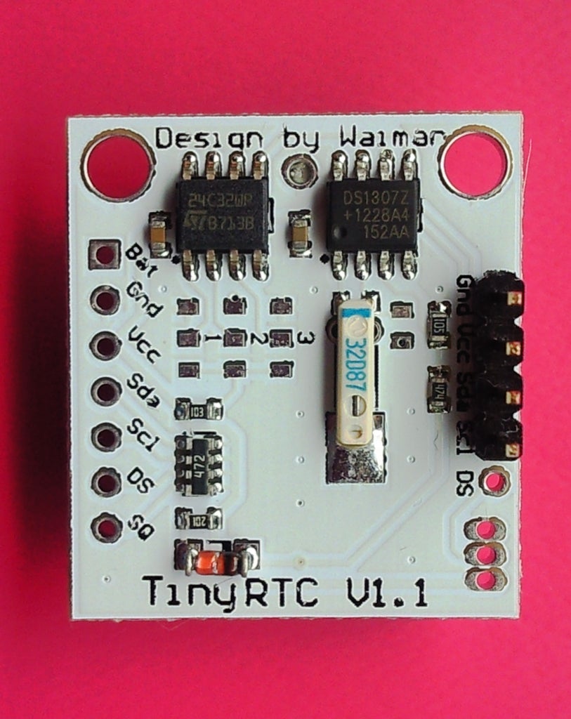

Before a couple of weeks I decided to implement additional functions in this shield. These functions had to be : the current time and date displayed on the LCD. For that purpose I bought a RTC module from ebay. (Shown on the pictures). This module is not very precise and it must be adjusted from time to time. The other solution is to try to change the quartz crystal with better one.
Step 6: The Shield Modification
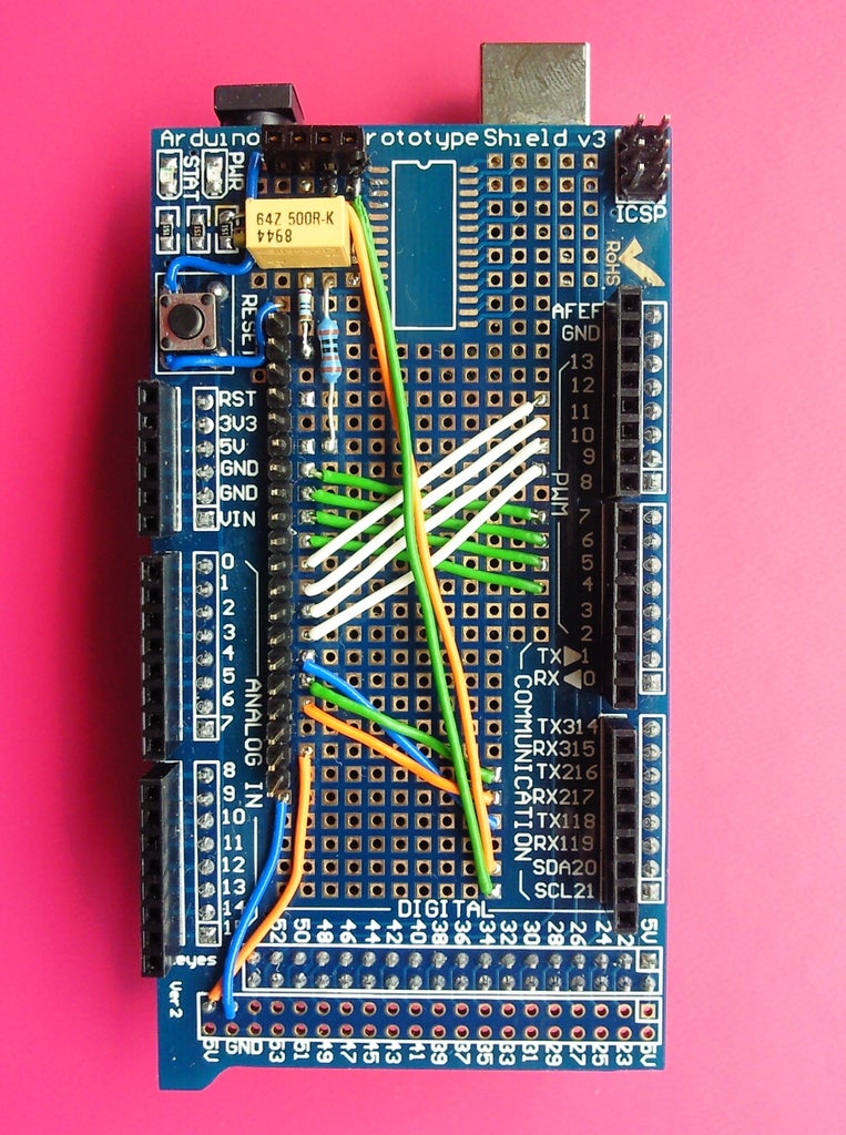
To be able to insert the RTC I have modified the shield in the following way: I have soldered a 4-pin female header, and connected it to the proper signals.
The SCL RTC pin is connected with pin # 21 of the shield/ arduino, respectively
SDA is connected with pin #20
Do not forget to connect the GND and Vcc pins.
Step 7: The Code...
The previous code was modified so:
/*
Thermometer based on Maxims DS600u+ chip + RTC
*/
#include "U8glib.h"
#include <math.h>
#include <Wire.h>
#include <DS1307.h>
int rtc[7];
float supply = 4.91; // Here must be entered the measured supply voltage of the arduino board
//read the sensor output voltage
char hours[2];
char minutes[2];
char seconds[2];
char days[2];
char months[2];
char years[4];
U8GLIB_ST7920_128X64_4X u8g(8, 9, 10, 11, 4, 5, 6, 7, 18, 17, 16); // 8Bit Com: D0..D7: 8,9,10,11,4,5,6,7 en=18, di=17,rw=16
void u8g_prepare(void) {
u8g.setFont(u8g_font_6x10);
u8g.setFontRefHeightExtendedText();
u8g.setDefaultForegroundColor();
u8g.setFontPosTop();
}
void setup(void) {
Serial.begin(9600);
// flip screen, if required
//u8g.setRot180();
// assign default color value
if ( u8g.getMode() == U8G_MODE_R3G3B2 )
u8g.setColorIndex(255); // white
else if ( u8g.getMode() == U8G_MODE_GRAY2BIT )
u8g.setColorIndex(3); // max intensity
else if ( u8g.getMode() == U8G_MODE_BW )
u8g.setColorIndex(1); // pixel on
//u8g.setContrast(0x30);
pinMode(13, OUTPUT);
digitalWrite(13, HIGH);
u8g_prepare();
}
void draw(void) {
u8g.drawFrame(0,0,127,63);
u8g.drawFrame(13,7,103,21);
u8g.drawBox(15,9,99,17);
RTC.get(rtc,true);
u8g.setColorIndex(0);
dtostrf(rtc[2],2,0,hours);
if (rtc[2]<10)
{
u8g.drawStr(26,14,"0");
}
u8g.drawStr(26,14,hours);
dtostrf(rtc[1],2,0,minutes);
u8g.drawStr(45,14,":");
if (rtc[1]<10)
{
u8g.drawStr(58,14,"0");
}
u8g.drawStr(58,14,minutes);
dtostrf(rtc[0],2,0,seconds);
u8g.drawStr(78,14,":");
if (rtc[0]<10)
{
u8g.drawStr(91,14,"0");
}
u8g.drawStr(91,14,seconds);
u8g.setColorIndex(1);
switch( rtc[3] )
{
case 1: u8g.drawStr(4,33," Sunday "); break;
case 2: u8g.drawStr(4,33," Monday "); break;
case 3: u8g.drawStr(4,33," Tuesday "); break;
case 4: u8g.drawStr(4,33,"Wednesday"); break;
case 5: u8g.drawStr(4,33,"Thursday "); break;
case 6: u8g.drawStr(4,33," Friday "); break;
case 7: u8g.drawStr(4,33,"Saturday "); break;
}
dtostrf(rtc[4],2,0,days);
if (rtc[4]<10)
{
u8g.drawStr(64,33,"0");
}
u8g.drawStr(64,33,days);
u8g.drawStr(75,33,".");
dtostrf(rtc[5],2,0,months);
if (rtc[5]<10)
{
u8g.drawStr(80,33,"0");
}
u8g.drawStr(80,33,months);
u8g.drawStr(90,33,".");
dtostrf(rtc[6],4,0,years);
u8g.drawStr(96,33,years);
int reading = analogRead(0);
float v_out = (reading * supply)/1.024;
// show on the LCD the temperature
float temperature = (v_out - 509)/6.45 ;
char temp[5];
dtostrf(temperature,5,1,temp);
u8g.drawStr(4,48,"Temperature:");
u8g.drawStr(76,48,temp);
u8g.drawStr(108,48,"\260C");
}
void loop(void) {
// picture loop
u8g.firstPage();
do {
draw();
} while( u8g.nextPage() );
// rebuild the picture after some delay
delay(1000);
}
As you see this code requires the library DS1307. I have attached this library to help you with the confusions caused by the different DS1307 libraries available.
This seems to be the end of the project :-).
Attachments

Participated in the
Epilog Challenge V

Participated in the
Arduino Contest


