

Introduction: DIY Cold Heat Soldering Iron


Or, how I learned to love the ohm.
Ohm, .. ohm. get it? its an electrical joke.. see.. never mind.
Yes folks, you too can make your own Cold Heat soldering iron!
Why spend $19.95 of your own hard earned money when you can make your own from the junk you have laying around. As a bonus, the unit you make will most likely be far more powerful than the commercially produced toy and much cheaper to maintain.
I have always been a "why buy it when you could build it" kind of person. I had seen the ads for the Cold Heat product for some time, but never really considered getting one until someone started asking about Christmas gifts (Thanks Matt). I looked up some reviews, and became fascinated in the "how".
We are playing with electricity and heat here. Please take all necessary precautions and be careful. I won't take responsibility for the scorch marks on the cat. Again.
If you're not interested in the science behind all this and just want to get to the meat, skip to step 4.
**NOTE** Many people have had ideas and recommendations (go figure). I'm going to treat this as an open project. I'll be positing improvements and failures at the end or the instructable. Check frame 10 for further developments. Now, back to the story..
Step 1:

Traditional soldering irons use a heated metal tip to melt solder into electrical joints. This concept works great, but it can have some drawbacks. If the iron is too large or powerful, it can easily overheat the joint and destroy the board or components being soldered.
Its also somewhat dangerous to have a chunk of metal sitting around at a flaming 250-400+ degrees. People can burn themselves, and sometimes others, like that one time in my basement. And once in the garage. And maybe a few times in the attic. Not that anyone can prove anything.
The science behind the Cold Heat concept for soldering is not magic. Its not alien technology. Its not even that mysterious. The scientific principles behind the tool have been used in everything from light bulbs to space heaters to building cars. It's all about the resistance.
Viva la resistance!!
Step 2: Viva La Resistance!

Or.. the concepts behind what we are doing.
The first thing to understand is the concept of electrical resistance. Our friend Wikipedia defines it as such:
Electrical resistance is a ratio of the degree that an object opposes an electric current through it, measured in Ohms. Its reciprocal quantity is electrical conductance measured in siemens. Assuming a uniform current density, an object's electrical resistance is a function of both its physical geometry and the resistivity of the material it is made from
Facinating.. now wake up..
One useful product of electrical resistance is that when you attempt to pass electricity through a conductor, the resistance generates an amount of thermal energy relative to the resistance and electrical force. In other words, It gets warm. The more electricity you shove through, the hotter it gets. Sometimes it can get hot enough to glow.
One example of this is light bulbs. The filament in the bulb is nothing more than a thin wire made of Tungsten. When you pass current through it, it gets so hot it glows.
Another example is space heaters. Most electric heaters have filaments made of nichrome or ceramic. They use just enough electricity to get the element hot, but not usually enough to glow.
The key to using electrical resistance for heating is to find an element that is conductive, has enough resistance to heat up, but is also thermal resistant, so it will not start on fire or dissolve. Now, normally I would think of Kryptonite or Wonderflonium. But as neither of those are real, and both are freaking out my spell checker, lets turn to a more humble (and cheap) work horse.
Graphite!
Step 3: Pencil Me In... for SCIENCE!

Yes, humble graphite. Once again we turn to our humble repository of all knowlege,:
The mineral graphite, as with diamond and fullerene, is one of the allotropes of carbon. It was named by Abraham Gottlob Werner in 1789 from the Greek (graphein): "to draw/write", for its use in pencils, where it is commonly called lead, as distinguished from the actual metallic element lead. Unlike diamond, graphite is an electrical conductor, a semimetal, and can be used, for instance, in the electrodes of an arc lamp. Graphite holds the distinction of being the most stable form of carbon under standard conditions. Therefore, it is used in thermochemistry as the standard state for defining the heat of formation of carbon compounds. Graphite may be considered the highest grade of coal, just above anthracite and alternatively called meta-anthracite, although it is not normally used as fuel because it is hard to ignite.
Note that in the description we have the three elements we were looking for. Its an electrical conductor, its hard to ignite and being a semi-metal, it has a usable amount of electrical resistance. In the form of lead refills for mechanical pencils, it has the advantage of being cheap.
So, how can we take the miracle of electrical resistance and the wonders of graphite and combine them into something magical and wondrous? You will see.. But first, on to the parts list..
Step 4: Parts List

What we are going to construct is still technically a resistance style soldering iron like a traditional iron, but instead of heating a metal tip to melt the solder and heat the joint, we will be heating the work directly. We need just a few simple parts. Many builders will have most of the parts already.
We need:
1. A power supply with low voltage and high amperage. Anything around 5-10v and 5+ amps should be sufficient. After scrounging, it occured to me: an old PC power supply! it has a 5v circuit rated for around 15 amps.
2. An old soldering iron or anything suitable for a handle.
3. Two small scraps of copper or brass. Any metal may do, but it's what I had.
4. A sliver of mica. You don't have mica? What the hell... ok.. Just use some plexi-glass, like I did. People have also recommended Glass or a slice of a ceramic light bulb socket. The thinner the material, the better. Somewhere around 1/8 to 1/16th of an inch would be good.
5. A few feet of 8 to 12 gauge wire.
6. A working solder gun (Yes, I understand the irony...)
7. some lead refills for a mechanical pencil (thickness doesn't matter)
8. Some tools, including a small file and a wire snips. The actual list of tools may vary slightly depending on the parts you scavenge and what kinds of destruction you must rein down upon them to get them to cooperate.
9. Electrical tape.
10. A Craftsman multimeter. Optional, but highly recommended. There is no better precision instrument available.
11. A variable resistor of some kind that can handle the 5V voltage coming out of the PSU. I was thinking a pedal from a sewing machine, or perhaps a standard rheostat of some kind. This is also optional and the demo here is made without one, but many people have made this recommendation.
Now pile all that together and go have a snack.. When you return, we begin the chaos.
Step 5: Always Leave a Tip.

To construct the tip, we need two small strips of copper and one strip of plexi. We are going to make a sandwich of metal>lead>plex>lead>metal
Cut the pieces somewhere in the area of 1/4 inch wide and 1 inch long. To cut the copper, I just used a pair of shears. To cu the plexi, I used my Craftsman table saw. Cutting a piece that small by hand with a regular plexi cuter would be .. dangerous.
Use your file to cut groves on either side of the piece of plexi. These grooves will hold the pencil leads. The groves should be deep enough to seat the leads, but no so deep that they are totally under the surface. The lead should sit just above the surface. You could also use a dremel with
a cutting disk. It would prob be faster and more precise.
Take the two pieces of copper and solder a wire, about 12 inches long, to each one.
Create your sandwich, (being very careful with the leads, they break easy). Gently wrap some tape on the back end, away from the lead. I only taped it about halfway up the metal to make it easier to change the leads out later. I just slide a blade in to pry it open a little and slide a new one in. Make sure your soldered connections are NOT TOUCHING. Each metal plate should be electrically isolated. If you make your pieces small enough, you could use a piece of heat shrink tubing instead.
If you have access to some other heat resistant non-metallic, non conductive material (like mica) that you can make the middle spacer out of, please feel free to experiment. Plexi is all I had on hand and works OK so far. I think it will melt though after some repeated use and it may be difficult to get the lead out.
*EDIT: Many people have recommended regular glass, Pyrex or a slice of ceramic light bulb socket for the insulator instead. All are MUCH better suggestions than plex. If you have this material on hand and are comfortable working it, I would say give it a shot.
This.... is your tip. Gently place it to the side and DON'T LOOK AT IT! Not yet....
Step 6: Time to Get a Handle on His...


OK.. for the handle I chose an old Craftsman soldering iron I had laying around. I have around 5-7 irons, so I had no problem sacrificing this one. The design was also ideal, as the tip and socket is removable. I removed the old socket at the top. Luckily, it had a set screw I could reuse to hold the new tip.
Once I was done taking the old iron apart, I was left with a plastic handle with a metal tube. You can use anything to hold the tip as long as it keeps your hands away from any electrical connection and won't cause any shorting problems. A nice stick and a ton of tape would work as well.
Take your assembled tip (Its OK to look now) and slide it into the handle so the tip is out about a half inch. You should be able to see some tape outside the barrel. I used a much larger set screw so I could tighten it with my fingers. The screw is holding it in such a way that it helps hold the "sandwich" together as well. The screw is sitting on the tape. It should be tightened so as to hold the tip firmly, but not actually work it's way through to the metal of the tip. You don't want it shorting on the barrel of the iron. I would consider putting a small plastic spacer in there for the screw to seat on, if you have the time.
Step 7: Atomic Batteries to Power..


OK.. no batteries, but we do need power!
Our power for the project will come from our dedicated and somewhat crappy AGI 230w PC power supply. This is nothing more than a standard PC power source, available from sh***y computers everywhere.
**make sure it's not plugged in** I should not have to say this, but people are people.. As a side note, one major advantage to the PC supplies it that they usually have integrated fuse or breaker protection. If you accidentally short it to the point that it passes too much current, it will just shut down for a while. Just be careful here.
There is a giant tangle of wire coming off this thing. Not to worry. We only need a few, and they are not that hard to identify. Look for the connector with 4 wires. A yellow, a red and two black. We only need the red and one black wire. Cut them free from the connector and make sure to tape up the cut ends on the connector. Just in case. We don't need any shorts to complicate things.
Strip about an inch of insulation off the wires. This will be the connection for your soldering iron. If you have one, It would be a good idea at this point to fire up the supply and verify your getting 5 volts with a multimeter.
But Photozz, you say.. I plug the power supply into the wall and it won't turn on!!!! *cries a little*
OK..OK.. calm down.. this is what's refered to as a switched power supply. It requires some minor black magic and sorcery to get it to turn on.. Place three candles in a triangle around the power supply. Light them and begin spreading sage leaves around in a circle. At this point, a chicken would be handy. If you don't have one, you can use a small cat. Hold the animal over your head and feed it a piece of cheese you have stored under you pillow for three days.
Or..you could just skip all that and place a small jumper wire across the green and black wires on the large connector. The fan should fire up and the power will be live. Please be careful around the wires and connectors.
If the supply works and your getting 5 volts (or thereabouts) we are ready to move on to connecting things together!
Step 8: A Marriage of Convenience


OK.. so we have a working power supply and a magical wand of solder (+3). Lets get these puppies together and give it a try.
Connect the two leads from the handle to the wires from the power supply. Make sure you use wire nuts or electrical tape. Soldering the connections is better, but I wanted to test it first before I made anything permanent. I can also add a longer cord and make it just slightly more usable.
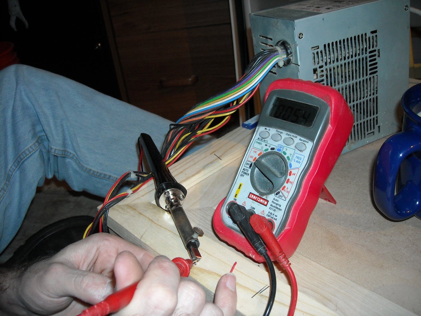
Make sure your tip is not shorted against anything and turn the power on. Take your multimeter and check the voltage across the pencil leads. It should register about 5v.
If not, check the two plates and make sure all your connections are good.
If everything checks out, you should be ready for some soldering!!
Of course for everything, there is a time and technique.
Step 9: A Little More to the Left...
Yes honey.. erm.. YES!.. Ok.. back to business.
First, some warnings.
1. You should not use this on anything that could be damaged by stray current or RF. You're using electricity to heat the components and it could cause the same problems as a static charge.
2. Don't press down. Pressing harder won't do anything but break the leads off. All you have to do is get both leads to touch the piece at the same time. This will heat up the work and melt the solder.
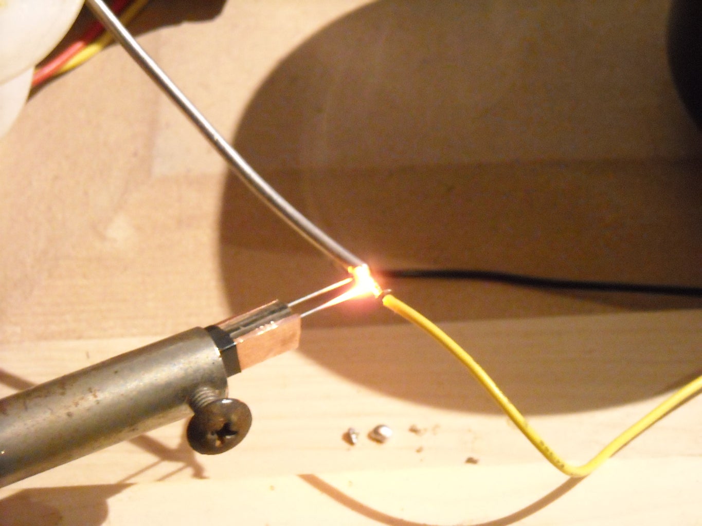
3. Careful how long you touch the piece. If the leads start glowing like light bulbs... too long dude... too long.
4. Be careful of stray voltage. I was holding the coil of solder and had my arm resting on the power supply. There was enough current passing into the solder to make a little buzz in my arm. Lets not do that again, shall we?
5. Practice.. Practice...Practice...and DON"T PRESS HARD!
I tested by soldering two wires together. I placed the two leads of the iron on either side of the joint, both touching bare metal. the leads started to glow and the metal heated up quite quickly. I touched a little solder in there and it flowed quite easily.
Success!
Now.. on to cure cancer.. but first.. conclusions and ideas..
Step 10: Wrapping It Like a Present...
Thoughts and ideas.. I'll add things here as I think of it, or as I discuss with people. I'll also post updates of further experiments and improvements.
The lead could be extended and if used carefully, it could be used to solder in places that many traditional irons could not reach.
This could be made into a tweezers. Pinching the part between the leads. Neato.
I should just replace the jumper wire on the power supply with a switch.
I could probably replace the PC supply with a battery pack. Sure, I would make it something like three car batteries on my back, but a few AA might work.
The tip does cool nearly instantly. The carbon radiates the excess heat off really quickly.
The middle spacer on the tip should really be something that won't melt. Let me know if you have any good ideas.
EDIT: Regular glass.. why didn't I think of that....
To regulate the power to the tip, I could use a simple rheostat. Something like a dimmer switch or the pedal from a sewing machine.
This is just a first pass at making something of this sort. Its delicate and somewhat unwieldy at the moment and I broke the lead at least three times while I was testing things. I leave it to you to make a better one. If I don't do it first.
I have now procured (Dumm dum dummmmmmmm) Two AA batteries I am going to strip for the carbon cores. If it works out OK, I'll update with pics and such.
This was fun and cheap.
Many thanks to my lovely future wife Jackie for picture-help. Come check out our other strangeness:
http://www.lovesickrobot.org
http://photozz.wordpress.com/
Finalist in the
Craftsman Workshop of the Future Contest


