

Introduction: DIY Driving Simulator


This project took about 3 months to completely finish. It acts as a gravity sensing light up "steering wheel" that allows the user to interact with driving games by tilting and turning the steering wheel. This is a great gift for tech people or anyone that is getting ready to drive. Later in the project I explain how you can take this project further to include gas and brake pedals, then with a little software modification, have a real working driving simulator. This setup converts forward tilt into the 'w' key, backward tilt into the 's' key, left tilt into the 'a' key, and right tilt into the 'd' key, although this can be modified to use arrow keys quite easily. I only used wasd because that is how I programmed my driving game in game maker. I teach you how to use real gravitational sensing potentiometers and then, for those of you like myself who can't afford to buy things of that nature, show you both where to find them in household items and how to build your own from scratch!
Step 1: The Gravity Sensing Potentiometer

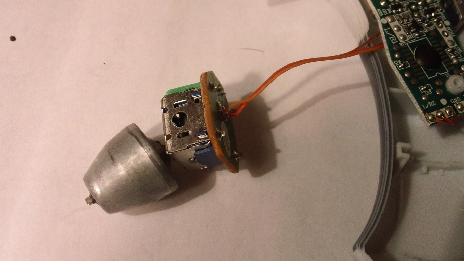
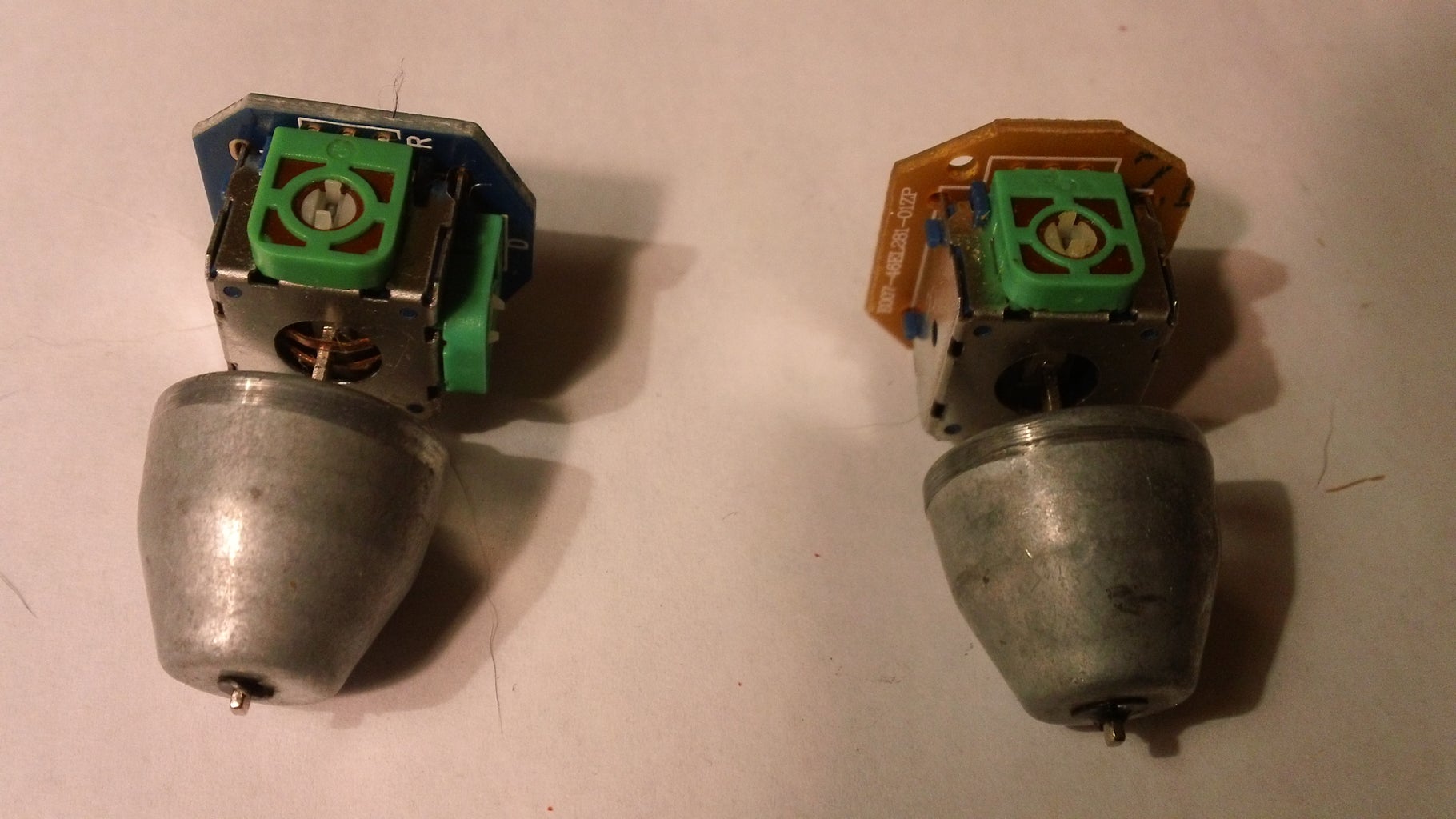


I found a commercial grade one in an old helicopter remote, but if you don't want to buy one, the next step tells you how to build your own one.
For the sake of people who are going to build their own one, I built my simulator sensor with one commercial sensor and one homemade sensor (you need 2 total)
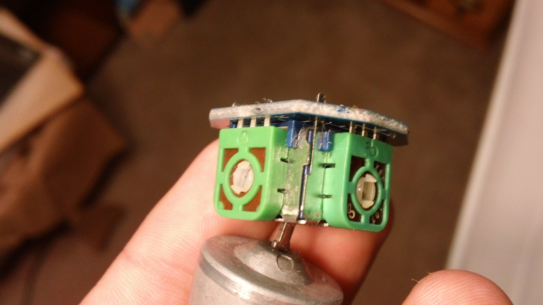
Step 2: Making Your Own Gravity Sensing Potentiometer


This step shows you how to create a perfectly working gravity sensing potentiometer from household parts
Get a potentiometer
Get a heavy and small ball
File down one side of the ball
Glue the knob onto the potentiometer
Glue the flat side of the ball onto the knob-make sure it is directly in the center of the knob
Glue a nut to the ball to add weight
Step 3: The Wheel


I found an old light up Frisbee but it did not have the ability to switch on and off the light, plus it came with pesky button cell batteries.
This step solves that problem by rewiring the Frisbee to have external battery power and a switch to turn the internal light on and off.
Connect wire to the positive and negative ends of the Frisbee circuit.
Wire up a switch and connect it between the battery and the circuit.
Glue everything down.
Step 4: The Casing

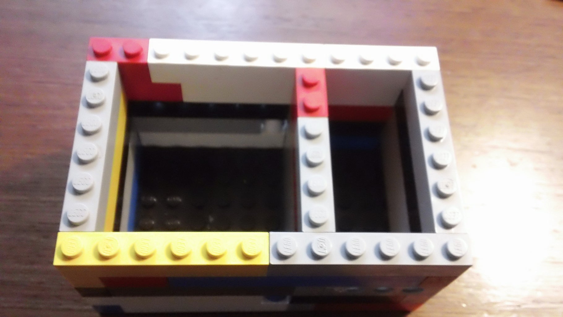


Bring out the legos!
12x8 box with 3x6 hole and 6x6 hole
these are used for up, down, left, and right sensor movement
The box should be 5 high
You can then fill in spaces so that the sensor is more compacted and directionally limited
Make sure to include holes for wires to come out
Step 5: Hooking Everything Up


Attach longer wires to everything so that you can use the wheel from a distance
Glue the sensors to plates and pack them into the holes in the Lego casing
Then attach Velcro to the underside and to the back of the "wheel"
Step 6: Optional Shield (Method One)


You can make your own "shield" using one of these two methods:
1: get some PCB and some pins and solder them to the board and solder on wires
Step 7: Optional Shield (Method Two)


2: get some pins and glue them or use silicon to fasten them to a plate. Make sure the pins line up with the diagram in the next step
Let the silicon dry for a day
I used cut safety pins and they worked well in the end
I used hot glue, then super glue, then silicon to match the strength of soldering
Step 8: The Diagram That Will Lead You on Your Way to Greatness

Do NOT mess up on this diagram. Make sure everything is correct before proceeding and plugging in the arduino.
Potentiometer 1 right goes to GND
middle goes to Analog 5
left goes to pin 4
Potentiometer 2 right goes to GND
middle goes to Analog 0
left goes to pin 8
Step 9: Programming (Arduino)

Arduino Code:
void setup(){
Serial.begin(9600);
pinMode(4,OUTPUT);
pinMode(8,OUTPUT);
}
void loop(){
digitalWrite(4,HIGH);
int d=analogRead(A5);
digitalWrite(4,LOW);
digitalWrite(8,HIGH);
int r=analogRead(A0);
digitalWrite(8,LOW);
int minimum=400;
int maximum=800;
Serial.println(d);
Serial.println(r);
//foreward tilt
if(d>maximum){
Serial.println('0');
}
else{
Serial.println('1');
}
delay(12.5);
//backwards tilt
if(d<minimum){
Serial.println('2');
}
else{
Serial.println('3');
}
delay(12.5);
//left tilt
if(r<minimum){
Serial.println('4');
}
else{
Serial.println('5');
}
delay(12.5);
//right tilt
if(r>maximum){
Serial.println('6');
}
else{
Serial.println('7');
}
delay(12.5);
}
Step 10: Programming (Python)

Python Code:
import serial
import codecs
import ctypes
import time
from time import sleep
SendInput = ctypes.windll.user32.SendInput
PUL = ctypes.POINTER(ctypes.c_ulong)
class KeyBdInput(ctypes.Structure):
_fields_ = [("wVk", ctypes.c_ushort),
("wScan", ctypes.c_ushort),
("dwFlags", ctypes.c_ulong),
("time", ctypes.c_ulong),
("dwExtraInfo", PUL)]
class HardwareInput(ctypes.Structure):
_fields_ = [("uMsg", ctypes.c_ulong),
("wParamL", ctypes.c_short),
("wParamH", ctypes.c_ushort)]
class MouseInput(ctypes.Structure):
_fields_ = [("dx", ctypes.c_long),
("dy", ctypes.c_long),
("mouseData", ctypes.c_ulong),
("dwFlags", ctypes.c_ulong),
("time",ctypes.c_ulong),
("dwExtraInfo", PUL)]
class Input_I(ctypes.Union):
_fields_ = [("ki", KeyBdInput),
("mi", MouseInput),
("hi", HardwareInput)]
class Input(ctypes.Structure):
_fields_ = [("type", ctypes.c_ulong),
("ii", Input_I)]
def PressKey(hexKeyCode):
extra = ctypes.c_ulong(0)
ii_ = Input_I()
ii_.ki = KeyBdInput( hexKeyCode, 0x48, 0, 0, ctypes.pointer(extra) )
x = Input( ctypes.c_ulong(1), ii_ )
ctypes.windll.user32.SendInput(1, ctypes.pointer(x), ctypes.sizeof(x))
def ReleaseKey(hexKeyCode):
extra = ctypes.c_ulong(0)
ii_ = Input_I()
ii_.ki = KeyBdInput( hexKeyCode, 0x48, 0x0002, 0, ctypes.pointer(extra) )
x = Input( ctypes.c_ulong(1), ii_ )
ctypes.windll.user32.SendInput(1, ctypes.pointer(x), ctypes.sizeof(x))
def PressW():
PressKey(0x57) #W
def ReleaseW():
ReleaseKey(0x57) #W
def PressA():
PressKey(0x41) #A
def ReleaseA():
ReleaseKey(0x41) #A
def PressS():
PressKey(0x53) #S
def ReleaseS():
ReleaseKey(0x53) #S
def PressD():
PressKey(0x44) #D
def ReleaseD():
ReleaseKey(0x44) #D
port = "COM6"
ser = serial.Serial(port, 9600, timeout=0)
while True:
#data = ser.read(9999)
line = ser.readline()
if line:
print( 'Got:', line)
if line==b'0\r\n':
print('W_UP')
PressW()
elif line==b'1\r\n':
print('W_DOWN')
ReleaseW()
if line==b'2\r\n':
print('S_UP')
PressS()
elif line==b'3\r\n':
print('S_DOWN')
ReleaseS()
if line==b'4\r\n':
print('A_UP')
PressA()
elif line==b'5\r\n':
print('A_DOWN')
ReleaseA()
if line==b'6\r\n':
print('D_UP')
PressD()
elif line==b'7\r\n':
print('D_DOWN')
ReleaseD()
sleep(0.0125)
print('0')
ser.close()
Step 11: The Game

Now you can either download my game from here or you can modify the python code to work for any other game!
If you have any questions about modifying the code for another game, message me or ask in the comments!
Step 12: One Step Further

If you want to go above and beyond, you can either make or use a pedal from an electric piano to act as a gas pedal/ brake pedal.
I wish you the best of luck and hope you succeed in creating your very own driving simulator because trust me, they are way better than using the keyboard keys to drive a car! In the future, I plan on using this concept to build a leg band that tracks movement and can use running movements to power internet speed etc. to make you have to work for that connection! Just imagine an new way of computer-body communication! Post in the comments or message me if you have any other applications for this sort of device!

Participated in the
UP! Contest

Participated in the
Holiday Gifts Contest

Participated in the
Instructables Design Competition


