Introduction: DIY Fingerprint Scanning Garage Door Opener

About: I am a master's student studying Electrical Engineering and an alumni of FIRST robotics. I also love to tinker on my own, which is mostly inspired by the amazing people on this website!

As a person without a car, I don't need to carry keys around everywhere I go. Because of this, I've been locked out of my own house several times. It's a pain to wait for someone with a key, so I thought I would do something about it.

This project is my way of solving this problem, while getting the chance to interface with an awesomefingerprint scanner (aka: FPS).

Also, this module isn't restricted to just garage doors, for you can create different kinds of simple motorized locks to suit your needs.

Step 1: Materials

Electronics:

PartSupplier (pictures are clickable!)
Fingerprint scanner (and JST connector)SparkfunSparkfun
Serial LCD kit (w/ATmega328)Sparkfun
ATtiny85Sparkfun
NPN transistorSparkfunRadioshack
BuzzerSparkfunRadioshack
Speaker wireRadioshack
3D printed caseSee step 9 for files
Copper tapeSparkfunAmazon
5V voltage regulatorSparkfunRadioshack
9V batterySparkfunRadioshack
9V battery connectorSparkfunRadioshack
SPDT limit switch
SparkfunRadioshack

Here is a list of almost all of the parts (It's a Sparkfun wishlist).

Tools:

  • Soldering iron/solder
  • Electrical tape
  • Hook up wire/ jumpers
  • Wire cutter/stripper
  • Perfboard
  • Assorted resistors
  • Screws
  • Drill
  • A few LEDs for testing
  • 5V FTDI board (Sparkfun)
  • Hot glue gun
  • Access to a 3D printer
  • Optional: IC holder (8 pin for ATtiny and 28 pin for ATmega)
  • Optional: Another Arduino board/10uF capacitor (see step 5 for details)

Step 2: The Circuit

The serial LCD kit sold by Sparkfun comes with an ATmega328 to control the LCD. The ATmega has extra processing power to be used for other tasks besides controlling the LCD. Because of this, we can use it as an Arduino to communicate with the fingerprint scanner, send an ATtiny85 commands, control the LCD, and use a buzzer to play tones.

To prevent the module from running continuously, I've added a limit switch to detect when the case is closed. If it's closed, power will not be supplied to it (saves battery power).

Important note:The fingerprint scanner communicates at a 3.3V level, so it is recommended to use a voltage divider to bring the signal from the ATmega to 3.2V. The voltage divider consists of a 560Ω resistor between D10/FPS pin 2 and a 1KΩ resistor between GND/FPS pin 2.

Serial LCD Pinout:

D10

FPS pin 1 (black wire)

D11FPS pin 2 (through voltage divider)
D12ATtiny85
D13Buzzer

ATtiny85 Pinout:

Pin 5 (0 in code)Input from ATmega
Pin 3 (4 in code)Transistor/yellow LED
Pin 7 (2 in code)Indicator LED

NOTE:A pull-down resistor is recommended on Pin 5 on the ATtiny for reliability (thanks to max921pointing it out)

Step 3: Assemble the Serial LCD Kit

Title says it all... This is a nice little kit to solder (I, personally, love to solder).

Sparkfun has a handy-dandy quick start/assembly guide if you would like.

You can optionally solder a 28 pin IC holder to the board, which will allow you to take the ATmega out and use it again in another non-LCD project.

Step 4: Assembling the Circuit Boards

The arrangement of the board is up to you, but remember to try to keep the FPS' wires facing the same direction so they don't break (they are really thin).

Next, I covered the the top and bottom with hot glue for both support and insulation. Using a high temperature hot glue is fine (nothing was burned/melted/ruined for me).

As with the main board, solder everything on the ATtiny's board together and optionally insulate/support it with hot glue. The voltage regulator might get a bit hot, so it would probably be a good idea not to let any hot glue get near it. You also might want to avoid covering the ATtiny in case you decide to take it out or reprogram it.

Step 5: Programing the ATmega328

As mentioned in step 2, the ATmega328 has enough processing power and pins to drive the LCD while driving other things. To take advantage of this, you will need to have some way to program the chip.

If you own an Arduino Uno or Duemilanove, you can simply take off the chip already on the board and replace it with the one provided in the kit. Alternatively, you can use Sparkfun's FTDI Basic Breakout (5V) and solder headers to the side (see the pictures of step 3 for details).

Also, you need to upload the code as a "Duemilanove w/ ATmega328."

See below for an example sketch to make sure it is working.

Code:

LCD Test:

//LCDTestExample by Nodcah 
//A simple sketch to make sure your Serial LCD Kit from Sparkfun
//is working

#include "LiquidCrystal.h"

LiquidCrystal lcd(2,3,4,5,6,7,8);

void setup() {
  pinMode(9, OUTPUT); //the backlight
  pinMode(13, OUTPUT); //the buzzer
  
  lcd.begin(16, 2); //16 chars wide, 2 tall
  
  digitalWrite(9, HIGH); //set the backlight to HIGH
  
  lcd.print("  Hello world!  "); //use spaces to center the text
  delay(2000);
}

void loop() { 
  //buzzer turns on and off and its status is displayed on the LCD
  lcd.clear();
  lcd.print("  Buzzer is on  ");
  tone(13, 262, 1000);
  delay(1000);
  lcd.clear();
  lcd.print(" Buzzer is off  ");
  delay(1000);
  }

Step 6: Setting Up the Fingerprint Scanner

For communicating with the FPS, I will use this Arduino library by Josh Hawley (direct download for the library here).

To make sure communication with your fingerprint scanner is working, I would upload this blink example.

The fingerprint scanner has its own memory to store the fingerprint data. So, after you have verified the fps is working, upload this example sketch to add your fingerprint to the database under id #0. Open the serial console and simply follow the instructions.

Code:

Blink Example:

/* 
 Library example for controlling the GT-511C3 Finger Print Scanner (FPS)
 Created by Josh Hawley, July 23rd 2013
 Licensed for non-commercial use, must include this license message
 basically, Feel free to hack away at it, but just give me credit for my work =)
 TLDR; Wil Wheaton's Law
 
 This simple sketch turns the LED on and off similar to the Arduino blink sketch.
 It is used to show that communications are working.
 */

#include "FPS_GT511C3.h"
#include "SoftwareSerial.h"

//Hardware setup - FPS connected to:
//digital pin 10(arduino rx, fps tx)
//digital pin 11(arduino tx - 560ohm resistor fps tx - 1000ohm resistor - ground)
//this brings the 5v tx line down to about 3.2v so we dont fry our fps

FPS_GT511C3 fps(10, 11);

void setup(){
  Serial.begin(9600);
  fps.UseSerialDebug = true; // so you can see the messages in the serial debug screen
  fps.Open();
}

void loop(){
  // FPS Blink LED Test
  fps.SetLED(true); // turn on the LED inside the fps
  delay(1000);
  fps.SetLED(false);// turn off the LED inside the fps
  delay(1000);
}

Enroll Example:

/* 
 FPS_Enroll.ino - Library example for controlling the GT-511C3 Finger Print Scanner (FPS)
 Created by Josh Hawley, July 23rd 2013
 Licensed for non-commercial use, must include this license message
 basically, Feel free to hack away at it, but just give me credit for my work =)
 TLDR; Wil Wheaton's Law
 */

#include "FPS_GT511C3.h"
#include "SoftwareSerial.h"

//Hardware setup - FPS connected to:
//digital pin 10(arduino rx, fps tx)
//digital pin 11(arduino tx - 560ohm resistor fps tx - 1000ohm resistor - ground)
//this brings the 5v tx line down to about 3.2v so we dont fry our fps

FPS_GT511C3 fps(10, 11);

void setup(){
  Serial.begin(9600);
  delay(100);
  fps.Open();
  fps.SetLED(true);
  Enroll();
}

void Enroll(){
  // Enroll test
  // find open enroll id
  int enrollid = 0;
  fps.EnrollStart(enrollid);

  // enroll
  Serial.print("Press finger to Enroll #");
  Serial.println(enrollid);
  while(fps.IsPressFinger() == false) delay(100);
  bool bret = fps.CaptureFinger(true);
  int iret = 0;
  if (bret != false)
  {
    Serial.println("Remove finger");
    fps.Enroll1(); 
    while(fps.IsPressFinger() == true) delay(100);
    Serial.println("Press same finger again");
    while(fps.IsPressFinger() == false) delay(100);
    bret = fps.CaptureFinger(true);
    if (bret != false)
    {
      Serial.println("Remove finger");
      fps.Enroll2();
      while(fps.IsPressFinger() == true) delay(100);
      Serial.println("Press same finger yet again");
      while(fps.IsPressFinger() == false) delay(100);
      bret = fps.CaptureFinger(true);
      if (bret != false)
      {
        Serial.println("Remove finger");
        iret = fps.Enroll3();
        if (iret == 0)
        {
          Serial.println("Enrolling Successfull");
        }
        else
        {
          Serial.print("Enrolling Failed with error code:");
          Serial.println(iret);
        }
      }
      else Serial.println("Failed to capture third finger");
    }
    else Serial.println("Failed to capture second finger");
  }
  else Serial.println("Failed to capture first finger");
}

void loop(){
  delay(100000);
}

Step 7: Programing the ATtiny85

The ATtiny85 is basically a cheap and small Arduino condensed onto one chip (aka: one of the best things ever)! It can be programmed with another Arduino, including the ATmega328 in the serial LCD kit.

In this project, it will be used to execute very simple commands: check for a signal from the ATmega and open the garage door if the signal is legitimate.

To program it, connect it as seen in the picture above. Then, download all of the required files and follow the instructions by High-Low Tech.

After uploading this code, pin 13 on the Arduino (build-in LED) should be set to HIGH to signify that the code is working.

Code:

Final Code:

//fpsAttiny by Nodcah
//Recieves a brief signal from the main module to close a relay

void setup(){
  pinMode(2,OUTPUT); //indicator led through 10K resistor
  pinMode(4,OUTPUT); //trasistor pin that opens the garage
  pinMode(0,INPUT); //input 
  delay(500); //give things time to start up
  digitalWrite(2, HIGH); //indicator LED
}

void loop(){

  if(digitalRead(0)){ //simple pattern to trigger the transistor 
    delay(125);
    if(digitalRead(0)==false){ 
      delay(55); //the timings are off because the ATtiny's timer isn't perfect
      if(digitalRead(0)){
        delay(55);
        if(digitalRead(0)==false){ 
          delay(55);
          if(digitalRead(0)){
            delay(55);
            if(digitalRead(0)==false){
              digitalWrite(4, HIGH); //transistor "presses" the button
              delay(1000);
              digitalWrite(4,LOW);
              digitalWrite(2,LOW);
              delay(1000);
              digitalWrite(2, HIGH);
            }
          }
        }
      } 
    }
  }
}

Step 8: The Final Code

Below is an Arduino program I have written for this project using the FPS and LCD libraries. I've done my best to write comments in code to describe what each part does, but if you have any questions, feel free to ask me!

After this code is uploaded, everything should be working. Now all that needs to be done it to integrate it!

WARNING: Some people weren't able to get the FPS library to work. If this is the case, you can try downloading an older version of the Arduino IDE here.

Code:

Code for ATmega238:

/**
 *FPSGarageDoorOpenner by Nodcah
 
 *Opens a garage door if the scanned fingerprint is in
 *the FPS' database of prints. 
 *
 *FPS_GT511C3 library created by Josh Hawley, July 23rd 2013
 *Licensed for non-commercial use, must include this license message
 *basically, Feel free to hack away at it, but just give me credit for my work =)
 *TLDR; Wil Wheaton's Law
 *
 * Version 1.00: Initial release
 * Version 1.01: Fixed bug with openning the garage door on boot and Attiny timing
 * Version 1.02: 
 + Made transmission between ATtiny and ATmega timing more reliable (line 115)
 + Names are now associated with an ID
 */

#include "LiquidCrystal.h" //for the screen
#include "FPS_GT511C3.h" //the fps (fingerprint scanner) library
#include "SoftwareSerial.h" //used by fps library

//Setting up the pins for the LCD and the fps
LiquidCrystal lcd(2, 3, 4, 5, 6, 7, 8); //pinouts for LCD
FPS_GT511C3 fps(10, 11); //RX, TX

boolean isFinger = false; //true if the fps detects a finger on the scanner

//output pins
const int buzzerPin = 13;
const int backlightPin = 9;
const int attinyPin = 12;
const String idNames[] = 
{
  "self","Bro", "Ryan", "Mom", "Dad", "Auntie", "Grandma", "Zeide", "Person", "person", "Thumb"};

void setup(){
  //set outputs
  pinMode(buzzerPin, OUTPUT);
  pinMode(backlightPin, OUTPUT);
  pinMode(attinyPin, OUTPUT);

  //for debugging
  //Serial.begin(9600);
  fps.UseSerialDebug = false; //set to true for fps debugging through serial

  //initializing the libraries
  lcd.begin(16,2);
  digitalWrite(backlightPin, HIGH); //the LCD backlight
  fps.Open();
  fps.SetLED(true); //the fps LED
  //boot up sound
  for(int i=0; i<30; i++){
    tone(buzzerPin, 50+10*i, 30);
    delay(30);
  }
  tone(buzzerPin, 350);

  //print starting message
  lcd.print("Put your finger "); //the command to print to the LCD
  lcd.setCursor(0, 1); //sets the cursor to the 0th column in the 1st row
  lcd.print(" on the scanner ");
  delay(150);
  noTone(buzzerPin); //stops the startup sound

}
void loop(){
  //scan and identify the finger when one is put on it
  waitForFinger();

  lcd.clear(); //clears the screen and sets the cursor to 0,0
  fps.CaptureFinger(false); //captures the finger for identification
  int id = fps.Identify1_N(); //identifies print and stores the id

  if(id <= 10){
    lcd.print(" Access granted "); //success message
    lcd.setCursor(0,1);

    //prints name when the garage is opening 
    String message = "  Hey " + idNames[id] + "!";
    lcd.print(message);

    tone(buzzerPin, 262, 1000);
    delay(1500);

    //sends a signal to open the garage door
    digitalWrite(attinyPin, HIGH); //first pulse syncs the delays (10ms)
    delay(5);
    digitalWrite(attinyPin, LOW);
    delay(3);
    digitalWrite(attinyPin, HIGH); //next two open the garage
    delay(15);
    digitalWrite(attinyPin, LOW);
    delay(5);
    digitalWrite(attinyPin, HIGH);
    delay(10);
    digitalWrite(attinyPin, LOW);
    delay(1000);

    lcd.clear();
    lcd.print("Don't forget to ");
    lcd.setCursor(0,1);
    lcd.print("  shut me off!  ");
    delay(2000);

    waitForFinger(); //tap to continue to enroll

    while(true){ //save a new fingerprint
      //prints message to lcd
      lcd.clear();
      lcd.print(centerText("So you want to"));
      lcd.setCursor(0,1);
      lcd.print(centerText("scan a new one?"));
      delay(2000);

      //Copied and slightly modified from the enroll example:
      int enrollid = 11;

      //choosing which id to overwrite/create
      //release your finger when you want to write to the id/name printed on the screen

      waitForFinger(); //waits for the fps to be pressed

      while(enrollid==11){
        for (int i = 1; i<=10; i++){
          if((fps.IsPressFinger() == true)){
            lcd.clear();
            String str = "ID " + String(i) + ": " + idNames[i]; //concats a string w/the id
            lcd.print(centerText(str));
            delay(1000);
          }
          else if(i>1){
            lcd.print(i);
            enrollid = i-1;
            break;
          }
        }
      }

      //warning if there is already data in this id slot
      if(fps.CheckEnrolled(enrollid)){ 
        lcd.clear();
        lcd.print(" Warning! ID #");
        lcd.print(enrollid);
        lcd.setCursor(0,1);
        lcd.print(" has data. OK?  ");
        delay(2500);

        waitForFinger(); //waits for the fps to be pressed

        fps.DeleteID(enrollid); //delete data
        delay(100);
      }

      //Enroll
      fps.EnrollStart(enrollid);
      lcd.clear(); 
      lcd.print("Place finger to ");
      lcd.setCursor(0,1);
      lcd.print("enroll #");
      lcd.print(enrollid); //prints id that is being enrolled
      waitForFinger(); //waits for the fps to be pressed

      //captures the finger and saves to memory three times for accurate data
      bool bret = fps.CaptureFinger(true); //high quality pic for enrollment
      int iret = 0; //error stuff

      if (bret != false){ //first enroll
        lcd.clear();
        lcd.print(" Remove finger  ");
        fps.Enroll1();
        while(fps.IsPressFinger() == true) delay(100); //waits until no finger
        lcd.clear();
        lcd.print("  Press again   ");
        waitForFinger(); //waits for the fps to be pressed
        bret = fps.CaptureFinger(true);

        if (bret != false){ //second enroll
          lcd.clear();
          lcd.print(" Remove finger  ");
          fps.Enroll2();
          while(fps.IsPressFinger() == true) delay(100);
          lcd.clear();
          lcd.print("Press yet again ");
          waitForFinger(); 
          bret = fps.CaptureFinger(true);

          if (bret != false){ //third enroll
            iret = fps.Enroll3();
            if (iret == 0){ //checks to see if there are any errors
              lcd.clear();
              lcd.print("    Success!    ");
              delay(2000);
              beep(); //shuts arduino off
            }
            else{ //if the enrollment fails in any way
              lcd.clear();
              lcd.print("Fail. Try again ");
              delay(1000);
            }
          }
          lcd.clear();
          lcd.print("   Failed 3rd   "); //error on 3rd
          delay(1000);
        }
        lcd.clear();
        lcd.print("   Failed 2nd   "); //error on 2nd
        delay(1000);
      }
      lcd.clear();
      lcd.print("   Failed 1st   "); //error on 1st
      delay(1000);
    }
  }

  else{
    lcd.print("Fingerprint is"); //if print isn't recognized
    lcd.setCursor(0,1);
    lcd.print("   unverified   ");
    delay(2000);
    lcd.clear();
    lcd.print("Please try again");
    lcd.setCursor(0,1);
    lcd.print("Use your pointer"); //I scanned everyone's pointer finger
    delay(500);
  }
  delay(250);
}


void beep(){ 
  //beeps in hopes of someone closing the case
  lcd.clear();
  lcd.print("Please close the");
  lcd.setCursor(0,1);
  lcd.print("     case!      ");
  for(int i=0;i<8;i++){
    tone(buzzerPin, 262, 500);
    delay(1000);
  }
  delay(5000); //wait for someone to close the case

  //if no one does, shut everything off
  lcd.clear();
  digitalWrite(backlightPin, LOW);
  fps.SetLED(LOW);
  while(true) delay(10000);
}

void waitForFinger(){
  static int timer; //contains timeout counter
  timer = 0; //resets the timer everytime this function starts
  while(!fps.IsPressFinger()){ //timeout of eight seconds
    timer++;
    delay(100); 
    if (timer>=80 && !fps.IsPressFinger()){
      beep();
    }
  } 
  timer = 0; //resets the timer everytime this function ends
}

String centerText(String s) { //centers text on the LCD to look better
  while(16-s.length()>1){ //if the text needs to be centered
    s = " " + s + " "; //creates space on both sides evenly
  }
  return s;
}

Step 9: The 3D Printed Case

To turn on the module, the case will need to be slid up, triggering the limit switch. As shown by the pictures, the limit switch needs to be wired to the common terminal (C), and the normally closed (NC) terminal.

Then, everything is glued to the case with hot glue. The limit switch is positioned with a slight tilt to make it easier to press.

Update (2/2/19): Thanks to JustinO60, there is a design outfitted for the new FPS that can be downloaded here (Main, Cover)

Step 10: Prepare the Garage

To open the garage door I wired the ATtiny85 to the button that normally opens the garage. Instead of a physical connection being made, the ATtiny uses a NPN transistor to "press" the button.

The wires should first be measured and cut to size, leaving a little extra wire just to be safe. Then, the hard part: soldering the wires from the button to the FPS module (shown in the pictures as an animated GIF). The wires should next be wrapped with a generous amount of tape.

To get the signal from the ATmega outside of the garage to the ATtiny inside the garage, three wires (power, ground and signal) will need to be fed through the wall. On my garage, there was a piece of wood that I just drilled right through (see the pictures).

Finally, screw on the case and boot it up!
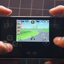
Step 11: Testing!

Now is the fun part! Use the module's built-in enroll feature so family/friends can open the garage. Then, create personalized messages for each one! Watch the video for a visual explanation of functionality.

Step 12: Making It Portable

The fingerprint scanner and LCD can be integrated into something like a chest, because it runs on batteries! I took the module off the garage door (temporarily), and combined with a servo to lock this chest with the power of my finger!

Note: I found the 9V battery above doesn't supply enough current to power the module and the servo, so I used 6 AA batteries instead. Also, my lock design is for display purposes only. To make this more secure, I would recommend using a more rigid design.

Sensors Contest

Grand Prize in the
Sensors Contest

Epilog Challenge VI

Grand Prize in the
Epilog Challenge VI

Battery Powered Contest

Participated in the
Battery Powered Contest