

Introduction: DIY Guitar Pedal


Making a DIY guitar fuzz pedal is a fun and easy electronics weekend project for hobbyists and guitarists alike. Making a classic fuzz pedal is much easier than you think. It just uses two transistors and a handful of other components. Aside from sharing the schematic, throughout this project I will also be going over basic tips and tricks for guitar pedal construction.
If you would like to learn more about electronics and reading schematics, check out the free Electronics Class!
Step 1: Materials

For this project you will need:
(x1) Hammond BB metal enclosure
(x2) 2N3904 transistors (or equivalent) *
(x1) 22uF capacitor
(x1) 0.1uF capacitor **
(x1) 0.01uF capacitor **
(x2) 100k resistors ***
(x1) 10K resistor ****
(x1) 5.1K resistor ***
(x1) 5K potentiometer
(x1) 100K potentiometer
(x1) DPDT heavy duty push switch
(x1) PCB
(x1) 9V battery plug
(x1) 9V battery
(x2) 1/4" stereo jacks
(x2) Dial plates
(x2) Knobs
(x2) Velcro squares
(x1) 3M 30-NF Contact Cement
(x1) Drilling guides (download and print)
* Different NPN transistors create slightly different sounds. Feel free to experiment on a breadboard with the circuit before you build it.
** The 0.1uF and 0.01uF capacitor can also be swapped out for slightly different values to create different sounds. Again, experiment on a breadboard before you solder anything in place.
*** Carbon film resistor kit. Only kit necessary for all labeled parts.
Please note that some of the links on this page contain affiliate links. This does not change the price of any of the items for sale. However, I earn a small commission if you click on any of those links and buy anything. I reinvest this money into materials and tools for future projects. If you would like an alternate suggestion for a supplier of any of the parts, please let me know.
Attachments

Step 2: Attach the Drilling Guides


Cut out the drilling guides and attach them with masking tape centered upon the top and side faces of the enclosure (as appropriate).
Step 3: Mark the Centers


Mark the centers of each hole using a punch (or a nail if you don't have one).
Drill pilot holes for each marking using a 1/8" drill bit.
Step 4: Drill 9/32" Holes


Widen all of the holes in the enclosure with a 9/32" drill bit (or appropriate for you potentiometers).
Step 5: Drill 3/8" Holes


Widen the holes in the side of the enclosure using a 3/8" drill bit.
Also, widen the center hole in front of the enclosure with the same drill bit.
Step 6: Drill a 1/2" Hole


Finally, widen the center DPDT switch hole in the front of the enclosure with a 1/2" drill bit. You will likely want to clamp the enclosure down to your work table (or in a vise), before you drill this hole. A 1/2" drill bit can be aggressive.
Step 7: Mark the Mounting Tabs


Insert the potentiometers into their front mounting holes backwards and upside down.
Wiggle, them back and forth, and notice you have scratched a line on the surface that corresponds to its mounting tab.
Drill a 1/8" hole along this line just to the left of the larger potentiometer mounting hole.
Step 8: Create a Stencil


Lay one of the front dial plates on a piece of painters tape.
Trace and cut out its outline.
Step 9: Place the Template


Center the front plate atop one of the potentiometer holes.
Place the tape template down around it, and stick it to the front surface of the enclosure.
Step 10: Glue Down


Apply contact cement to the center of the stencil and also the back of the front dial plate.
Wait for it to dry long enough to become tacky to the touch.
Once dry, press the dial firmly to the enclosure to glue it in place.
Step 11: Repeat

Repeat the process for the second dial.
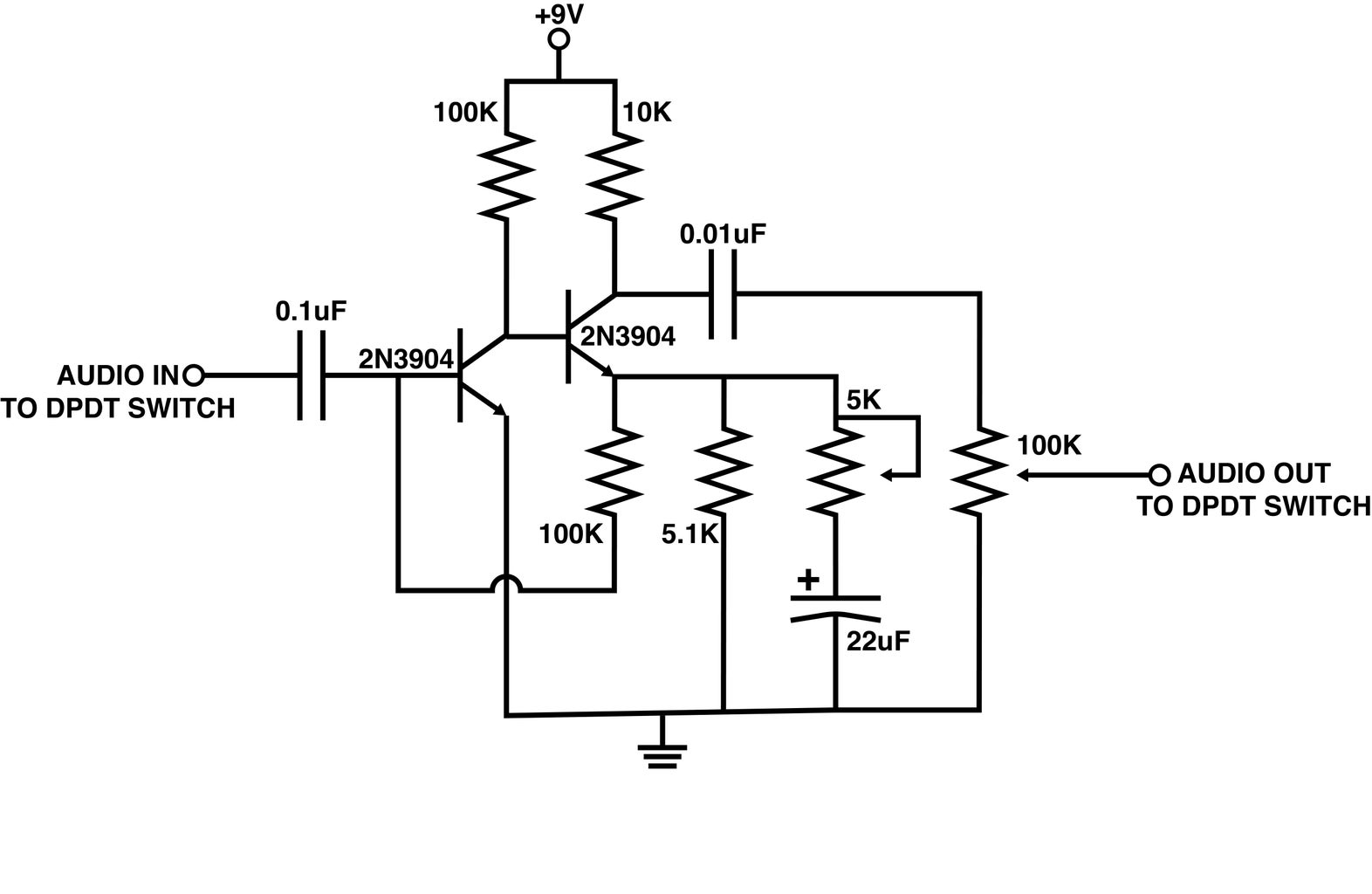
Step 12: Build the Circuit


Build the circuit as specified in the schematic. For now, do now worry about wiring jacks, potentiometers, or anything else that might not attach directly to the circuit board.
This circuit is basically a 2-transistor gain circuit and a variation on the classic Fuzz Face guitar pedal. To learn more than you ever wanted to know about this circuit, check out R.G. Keen's Technology of the Fuzz Face article.
Step 13: Wire the Potentiometers

Solder 5" green wires to the center and right-hand pin (if the potentiometer knob is facing you) on both potentiometers.
Also solder a 5" black wire to the remaining outer pin on the 100K potentiometer.
Step 14: Mount the Potentiometers


Mount the potentiometers to the enclosure by inserting it's shaft up through the hole in the enclosure, and fastening it in placing with its mounting screw.
Step 15: Wire the Power and Jack

Connect a 5" black wire to the terminal connected to the center barrel jack.
Connect the black wire from the 9V battery clip to the terminal connected to the smaller signal tab.
Finally, connect a 5" green wire to the terminal connected to the longer signal tab.
Step 16:


Mount the jacks and potentiometers to the inside of the enclosure using their mounting nuts.
In my pedal, the input and gain pot will be on the left of the pedal, and the 100K volume pot and output jack will be on the right.
Step 17: Mount the Switch


Mount the switch to the enclosure using its mounting hardware.
Step 18: Wire the Switch

Connect one of the switch's center pin to the green wire connected to the audio / power jack.
Wire the other center pin to the identical pin on the other audio jack.
Wire together one set of outer pins.
Solder a wire between the remaining pin in-line with the output jack to the center pin on the volume potentiometer.
Finally, solder a green wire to the remaining free pin. This will later be attached to the circuit board.
Step 19: Ground Connection

Connect the black ground wire from the volume potentiometer to the terminal on the audio jack connected to the barrel.
It is important to understand what is happening here, and that it will only work with a metal enclosure. Basically, since the other jack is using the barrel connection as a switch for the ground, the entire case is electrically connected to the ground plane. Thus, the barrel jack on the other jack is also connected to ground. So, by connecting the potentiometer to it, you are effectively connecting it to ground on the circuit board (without actually attaching it to the circuit board).
Step 20: Wire the Circuit Board


Now is time to attach the components mounted to the enclosure to the circuit board.
The red wire from the 9V power clip should go to the power rail, and the black wire from the stereo jack should be attached to the ground rail.
The gain potentiometer should be attached as specified in the schematic.
Lastly, the remaining unconnected switch wire in-line with the input should be connected to the input on the circuit, and remaining wire from the volume potentiometer should be connected to the output on the circuit board.
Step 21: Velcro


Attach the circuit board to the bottom of the enclosure using self-adhesive Velcro tabs. This both holds it in place,
and prevents it from touching the lid and shorting the circuit.
Step 22: Shut the Enclosure


Plug in the battery if you have not done so already and fasten the lid onto the enclosure using its mounting screws.
Step 23: Attach the Knobs


Turn the potentiometer knobs counter clockwise until they stop turning.
Place the knobs in place with their pointers pointing at the starting position on the dial.
Fasten the knobs in place with their set screws.
Step 24: Plug In

You are now ready to plug everything in and rock out.

Did you find this useful, fun, or entertaining?
Follow @madeineuphoria to see my latest projects.


