

Introduction: DIY Home Automation With ESP8266 (Linknode R4) and Amazon Alexa


Over the last year or so I have became captivated with anything and everything ESP8266 related, and rightfully so. This little WiFi module is everything I have been hoping for in a development board for years. It’s small and compact, and has built in WiFi, as well as several GPIO lines, and is Arduino IDE compatible making reading sensors and controlling things like relays and such very easy. In this review / overview I am going to take a look at the Linknode R4, a new offering from LinkSprite, a fairly young company that is dedicated to offering the public affordable DIY home automation solutions.
Step 1: About the LinkNode R4

The Linknode R4 is a 4-channel relay board that features an ESP8266, a low-cost Wi-Fi chip with full TCP/IP stack and MCU built in that has taken the maker world by storm over the last two years. The Linknode R4 features four Songle 10A 240/120V AC relays that operate on 5V DC coils. The board is powered via an external 5V 2A+ source (not included), and must be programmed with an USB TTL UART cable such as those made by FTDI, or an Arduino acting as an ISP via its UART pins. Each relay features a three-pin screw jack terminal to safely secure and insulate the mains voltage lines that are meant to connect to them.
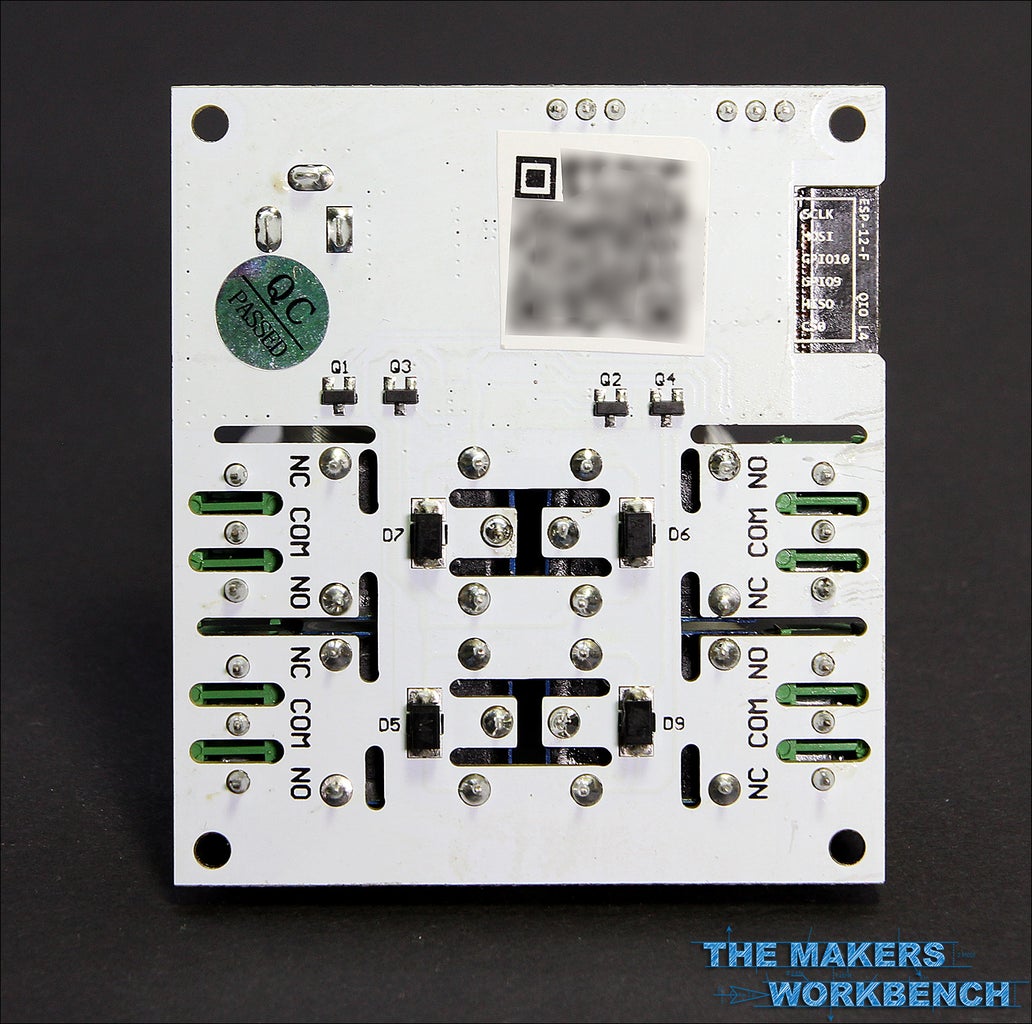
Looking at the board from the bottom we can see that LinkSprite has taken the precautions necessary to isolate the high voltage AC lines from each other by routing out slots between each trace. This is a very nice feature, and I often find lacking on cheap Chinese relay boards that I often buy from AliExpress or Ebay. LinkSprite has also routed out the FR4 PCB material directly below the ESP8266’s WiFi antenna. This is necessary, as the copper cladding would block any radio waves that might come from behind the board. Note that I have blurred out the QR code and board ID number as they are unique to this board, and used when connecting the board to the LinkSprite Cloud service.
Step 2: LinkNode R4 Pinouts

As you can see from the diagram above, the LinkNode R4 utilizes only three of the GPIO that the ESP8266 offers, and I am going to deduct a few points for this. There is enough real estate space on the PCB to break out the rest of the pins, and while a good many of this boards users may never use them, there are those like me who would like to use them for things like motion sensors, temperature and humidity sensors, and anything else we can use a digital GPIO pin for. It just seems so simple to add a few through hole solder points that break out the rest of the GPIO, and a few GND, 3.3V and 5V pins. They would not even need to be populated as that is something the end user could easily do themselves.
Additionally, you can see that the Linknode R4 uses GPIO pins 12, 13, 14, 16, which can be a little confusing and hard to figure out if you do not visit the board’s Wiki page on the LinkSprite website. I would have liked to see this information printed on the silkscreen layer of the PCB, but it is not. Although, I do understand that the rational behind this information being missing from the PCB, as most of the consumers who purchase this board will be more focused on its “out of the box” control using dedicated Android and IOS apps.
Step 3: The LinkNode R4's Firmware and Why I Am Not a Fan

I have mixed feelings about the firmware that ships with the LinkNode R4, mainly because I was unable to get it working again after flashing my own custom firmware to the ESP8266, and then trying to return to the original code. Out of the box, the LinkNode works well with the software, and its cloud-based API, but I did notice a slight delay of about 1-second when toggling the relays on and off. I attribute this to the latency that induced from having your phone send the data to the LinkSprite cloud, and then the cloud relaying that data to the LinkNode itself. I also noticed that this delay varied some during different hours of the day, which is most likely caused by the internet usage load that fluctuates in my neighborhood.
I had originally planned on reviewing this board using its stock firmware, and showing off the app’s control functionality, but I failed to get footage of the app working before I flashed to my custom firmware. I downloaded the updated stock firmware from the LinkNode Github page , but was unable to get this code to work as the original code worked. After entering all of the correct information, and spending several hours debugging and troubleshooting, I determined that there was something on LinkSprite’s end that was not sending the correct packets back to the LinkNode R4, and watching the serial monitor confirmed this. The code was hanging at a section of the code where it awaits a response from the LinkSprite Cloud, and then stores the response in a txt file on the ESP8266.
+ delay(200);
+ Serial.println("Store response...");
+ String request = "";
+ while (client.available())
While watching the serial monitor it would just repeat “Store Response” and would never time out. I am not exactly sure why this happened, and I have contacted LinkSprite about this issue. With that part of the review dead in the water, I decided to have some fun and write some code that would allow me to control the LinkNode R4 with Amazon’s Alexa digital assistant since I picked up an Amazon Echo Dot on Black Friday. Before I share the code that I wrote to do this, I want to take a moment to show you how to program the LinkNode R4 using an FTDI cable.
Step 4: Programming the LinkNode R4 With the Arduino IDE : Part 1 - Download Arduino

Follow the next several to download the Arduino IDE, and prepare it to program the ESP8266.
Before you get started you will need to download the latest version of the Arduino IDE here.
Step 5: Programming the LinkNode R4 With the Arduino IDE : Part 2 - Install ESP8266 Package

- Once Arduino has been installed, run the program, and navigate to File > Preferences
- Enter this URL “http://arduino.esp8266.com/stable/package_esp8266com_index.json” into the Additional Board Manager URLs field.
Step 6: Programming the LinkNode R4 With the Arduino IDE : Part 3 - Install ESP8266 Package Continued
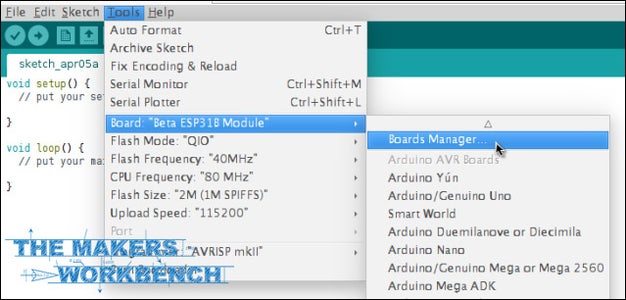
Open the Boards manager that is located in Tools > Board Menu > Boards Manager
Step 7: Programming the LinkNode R4 With the Arduino IDE : Part 4 - Install ESP8266 Package Continued 2

Search and install the esp8266 platform (and don't forget to select your ESP8266 board from Tools --> Board menu after installation).
Step 8: Programming the LinkNode R4 With the Arduino IDE : Part 5 - Install ESP8266 Package Continued 3

Double check the board configuration and match it to the image above. The LinkNode R4 has not been added into the official ESP8266 Arduino core repository yet, and this means that you will not find it listed in the ESP8266 board list. Don’t worry though, you can just Generic ESP8266 Module, and then set the Flash Mode to QIO.
Step 9: Programming the LinkNode R4 With the Arduino IDE : Part 5 - Install ESP8266 Package Continued 4
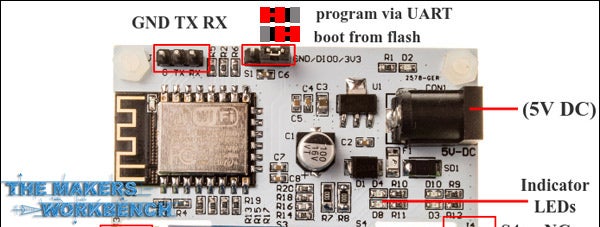
Remember to set the port that your FTDI cable is connected to,and then connect its TX, RX, and GND pins to the corresponding pins on the LinkNode R4. This number will vary from device to device, and may change every time you plug in the cable. Also remember to set the jumper pin from the boot from flash position to the program via UART position as shown in the image above. If the pin jumper is placed on the left and middle pins, it is ready to program. Remember to set this back to the boot from flash position when done.
That’s it! You are now set up to code the ESP8266 on the LinkNode R4 using Arduino code and the Arduino IDE. I did experience a memory error when uploading to the LinkNode R4 after uploading my code a few times. I am not sure why this happens, but it is a bug on every ESP8266 board that I have used over the past couple of years. If you experience this issue, just unplug the 5V power source, and the FTDI Cable, then reconnect everything and try again. It usually works after this is done the first time, but it may take a few tries.
Step 10: Controlling Your LinkNode R4 With Amazon Alexa and the Echo Dot.
I will not be sharing all of the files needed to get the LinkNode up and running with Amazon Alexa here as it would be a lot of code, and because I am still developing the code to be more streamlined, and efficient.Please visit my GitHub to download a zip archive of all of the necessary files needed.
**Note that the code below will not compile, or upload without these additional files, so head over to my GitHub to grab them all.
I will share the main Arduino sketch that I used so that you can have an idea of how everything ties together. I won't break down the entire code, but I will point out that I am creating four callbacks with unique names, four switches with unique names, and four integers which define the relays. I am also defining four unique invocation names for Alexa to understand, which are mapped to separate ports on the web server, and each unique invocation name has two settings, On and Off. Finally, I set the pinmode for each of the four relay pins as an output. Then it is as simple as setting up eight different functions for each relay. When Alexa hears “Turn on lightOne” for example, the ESP8266 runs the lightOneOn function. There is a lot more that goes on with the code that handles the FauxMo Belkin WeMo emulation, and to be quite honest, I am not fully sure that I understand every aspect of it just yet. I do know that it works, and adding new devices (up to 14 is supported by WeMo and Alexa) is as easy as duplicating the things I mentioned above, and giving each new device a unique name. So without further ado, here is the Arduino sketch that makes the magic you saw in the video above work. Remember that this code is useless without the other five files that can be found on my Github repo for this project.
-------------------------------------------------------------------------------------------------------------------------------------------------
#include
#include
#include
#include
#include "switch.h"
#include "UpnpBroadcastResponder.h"
#include "CallbackFunction.h"
// prototypes boolean connectWifi();
//on/off callbacks
void lightOneOn();
void lightOneOff();
void lightTwoOn();
void lightTwoOff();
void outletOneOn();
void outletOneOff();
void outletTwoOn();
void outletTwoOff();
// Change this before you flash const char* ssid = "YOUR SSID"; const char* password = "YOUR SSID PASSWORD";
boolean wifiConnected = false;
UpnpBroadcastResponder upnpBroadcastResponder;
Switch *lightOne = NULL;
Switch *lightTwo = NULL;
Switch *outletOne = NULL;
Switch *outletTwo = NULL;
// Set Relay Pins
int relayOne = 12;
int relayTwo = 13;
int relayThree = 14;
int relayFour = 16;
void setup()
{ Serial.begin(115200);
// Initialise wifi connection
wifiConnected = connectWifi();
if(wifiConnected){ upnpBroadcastResponder.beginUdpMulticast();
// Define your switches here. Max 14 //
Format: Alexa invocation name, local port no, on callback, off callback
lightOne = new Switch("Light One", 80, lightOneOn, lightOneOff);
lightTwo = new Switch("Light Two", 81, lightTwoOn, lightTwoOff);
outletOne = new Switch("Outlet One", 82, outletOneOn, outletOneOff);
outletTwo = new Switch("Outlet Two", 83, outletTwoOn, outletTwoOff);
Serial.println("Adding switches upnp broadcast responder");
upnpBroadcastResponder.addDevice(*lightOne);
upnpBroadcastResponder.addDevice(*lightTwo);
upnpBroadcastResponder.addDevice(*outletOne);
upnpBroadcastResponder.addDevice(*outletTwo);
//Set relay pins to outputs
pinMode(12,OUTPUT);
pinMode(13,OUTPUT);
pinMode(14,OUTPUT);
pinMode(16,OUTPUT);
}
}
void loop()
{
if(wifiConnected){ upnpBroadcastResponder.serverLoop();
lightOne->serverLoop();
lightTwo->serverLoop();
outletOne->serverLoop();
outletTwo->serverLoop();
}
}
void lightOneOn() {
Serial.print("Switch 1 turn on ...");
digitalWrite(relayOne, HIGH); // sets relayOne on
}
void lightOneOff() {
Serial.print("Switch 1 turn off ...");
digitalWrite(relayOne, LOW); // sets relayOne off
}
void lightTwoOn() {
Serial.print("Switch 2 turn on ...");
digitalWrite(relayThree, HIGH); // sets relayOne on
}
void lightTwoOff() {
Serial.print("Switch 2 turn off ...");
digitalWrite(relayThree, LOW); // sets relayOne on
}
//sockets
void outletOneOn() {
Serial.print("Socket 1 turn on ...");
digitalWrite(relayFour, HIGH); // sets relayOne on
}
void outletOneOff() {
Serial.print("Socket 1 turn off ...");
digitalWrite(relayFour, LOW); // sets relayOne off
}
void outletTwoOn() {
Serial.print("Socket 2 turn on ...");
digitalWrite(relayTwo, HIGH); // sets relayOne on
}
void outletTwoOff() {
Serial.print("Socket 2 turn off ...");
digitalWrite(relayTwo, LOW); // sets relayOne on
}
// connect to wifi – returns true if successful or false if not
boolean connectWifi(){
boolean state = true; int i = 0;
WiFi.mode(WIFI_STA);
WiFi.begin(ssid, password);
Serial.println("");
Serial.println("Connecting to WiFi");
// Wait for connection
Serial.print("Connecting ...");
while (WiFi.status() != WL_CONNECTED) {
delay(500);
Serial.print(".");
if (i > 10){
state = false; break;
}
i++;
}
if (state){
Serial.println("");
Serial.print("Connected to ");
Serial.println(ssid);
Serial.print("IP address: ");
Serial.println(WiFi.localIP());
}
else {
Serial.println("");
Serial.println("Connection failed.");
}
return state;
}
---------------------------------------------------------------------------------------------------------------------------------------
Step 11: Wrapping It Up

So that is going to wrap up this project for now. If you are interested in seeing more videos, and reading more tutorials / reviews like this, please head over to my YouTube Channel, and click on the subscribe button. Also remember to click the like button on the video above, and to leave me a comment on what you thought about this project. Stay tuned for more Amazon Alexa, and Linknode R4 related content. I have a whole series planned out, that will culminate in my entire office being automated. You can find my original writeup of this tutorial over at my website, The Makers Workbench.com.
If you would like more tutorials such as this, just let me know in the comments. Additionally, if you would like to see more tutorials like this from me posted here at Instructables, head over to my Patreon page and consider donating monthly to help us keep the lights on. Every donation counts, and with your support, we can continue to post a couple of tutorials each week.

Runner Up in the
Arduino Contest 2016


