

Introduction: DIY Keypad Matrix From the Principle of Operation to Implementation


Keypad Matrix !!
Ain't that sounds cool. Well that's a very simple voltage divider using resistors of various values .
Introduction :
Most electronic keyboards used in synthesizers, electronic organs, and digital pianos use a keyboard matrix circuit.
Why keypad matrix??
Without a matrix circuit, a 61-key keyboard would require 62 wires to connect (one for each note, and a ground) — an awkwardly thick bundle of wiring. With a matrix circuit, any of 61 notes can be determined with only 16 wires. This is drawn schematically as a matrix of 8 columns and 8 rows of wires, with a switch at every intersection. The keyboard controller scans the columns. If a key has been pressed, the controller scans the rows — and in a manner analogous to the board game "Battleship!", the controller determines the row-column combination at which a key has been pressed, and generates a note corresponding to that key. This process occurs so quickly that the performer is unaware of any delay
Step 1: Components Required


1. Microswitch
2.100pF Capacitor
3. Digital Multimeter
4.Jumper wires
5. Bread board
6. .25 W resistor of value (in ohms) - 1K, 1.5k, 3.3k, 470, 330, 560, 820
Step 2: How It Works


Lets build the circuit step by step and under stand how it works.
Step 1. Building the first column with two rows (2X1 matrix) :
A keypad matrix is actually a voltage divider circuit. A m X n keypad matrix has m rows and n columns . Across the micro switch resistances of different values are connected . In step one in the above figure we observe two resistances R1 and R2 are connected in series and across them the micro switches are connected .The biasing of the switches are shown .
Case 1 depicts the situation when microswitch 1 (M1) is pressed the current makes its way through the battery, R1, M1 and to the ground.
Case 2 depict the situation when M2 is pressed the current makes its way through the battery, R1, R2, M2 to ground.
Note that in each case different configuration of resistors gets connected hence each case is associated with different resistance hence the total current flowing in each circuit configuration is different which is taken in for analog reading.
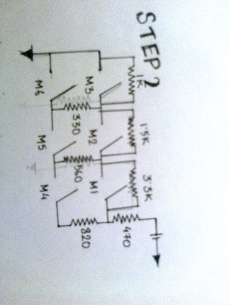
Step 2. Building the 3X2 matrix
Note I have kept different orders of resistances the ones connected across the first row are of orders of kilo ohms and the ones across the columns are kept smaller the logic behind doing this will become clear when we take up case 1 .NB current flows through least resistive path.
Case 1. When M5 is pressed the current first goes through 470 ohms. 3.3k .Then at this node it thinks which node is providing less resistance since its 560 is less than 1.5k (1500) ohms so it takes that path then its makes its way through 330 and finally 1k
Case 2. When M2 is pressed the current makes it way through 470 , 3.3k .then since a closed switch provides zero resistance so it bypasses 1.5k and makes its way through 1k to the ground .
Then White jumper wire is connected to GND the red is connected to 5V and then the other white jumper besides the GND is fed into the analog input terminal.
Step 3: Program for Arduino
The simple sketch of analog read serial out is used for noting down the analog read outs . Then corresponding to the read values the values are taken for example
M1------------ 592
M2------------ 269
M3------------ 179
M4------------ 247
M5------------ 159
M6------------ 59


