

Introduction: DIY LCD Backlight


This simple method lets you make LCD backlight of any color and size to bring new look to an old device.
Step 1: Let's Make Something.

For this job you'll need piece of transparent plastic, LEDs, resistors and some wire plus good set of different tools and couple of straight hands ;-)
Step 2: Take It Apart.

LCD consists of PCB, metal frame and liquid crystal glass assembly.
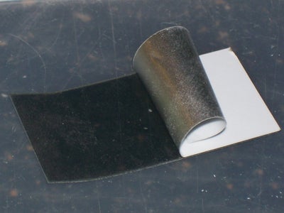
Step 3: Pull the Skin Off.

Back side of LCD glass is covered with very thin reflective film, which should be removed.
Step 4: Oops! Don't Rush! Think First.
My mistake was that I've removed polarizing filter together with reflective film.
If it happened just use sharp tool to separate them and save filter to put it back later.
See wiki for details.
http://en.wikipedia.org/wiki/Liquid_crystal_display
Step 5: Get It Cut.

Next cut rectangle piece of plastic.
Sand face and back sides of plastic plate with fine sandpaper to diffuse light then cut notches on sides of plate where you plan to install LEDs.
Shape of LED should be formed with file to fit into the notch
Step 6: Let's Practice Some LEGO ;-)

Something like that.
You can use hot glue to secure it on place.
Step 7: Let's Give It a Trial...

Not bad for me ;-)
Step 8: Bring All Bunnies Into the Cage.

Now everything is ready to be assembled:
-PCB;
-white sheet of paper to reflect light back;
-polarizing filter (if you removed it by mistake);
-plastic plate with embedded LEDs;
-glass assembly;
-frame.
NOTE:
Be very careful with golden pads on PCB and elastomer connector (zebra strip). Use pure alcohol to clean it if you touched contact pads with your fingers.
Another important thing is proper alignment.
If after powering it up you got missing lines (characters) on LCD then connector has shifted from original position. Carefully take it apart and re-align it.
Step 9: Final Step.


I hope you already calculated value of resistors you need.
So, solder it up.
There are two points to get power to LED from.
You can connect it directly to logic power supply (pin 0 - GND, pin 1 - 5V) of LCD.
Or you can make separate connection(on my LCD there were unused pads for optional backlight) and in that case you'll be able to use PWM signal to control brightness of LED.
Step 10: One More Example


I've used similar technique to modify antique analogue meter for my next project.
Participated in the
The Instructables Book Contest


