

Introduction: DIY Motion Sensor Alarm System


Are you constantly being scared when people sneak up behind your back? Do you have bad hearing and can't hear people approaching you? Do you want to just build a super fun Arduino project?
If you answered yes to any of those questions, then this project is for you! I have a workbench in my basement that I use all of the time for homework and projects. The bench is right next to my furnace which is very loud when running. Whenever someone comes in my basement, it scares the life out of me. I made this to alert me when someone is coming. This is a motion alarm system that alerts you whenever motion is detected around you. It uses an Arduino Uno to control the PIR motion Sensor, LED, and the speaker. It is all enclosed and fits in a box from a deck of cards! It is powered using the USB power cord for the Arduino. To program the Arduino, you can make your own sketch, or use mine in the upcoming step. The whole project will probably only take you a day or two and anyone should be able to do it. I am 14 years old, and lacking the ability to buy a lot of parts, so I try to do the best with what I have.
Step 1: Tools and Materials


Not many materials or tools are required for this project. I only spent about $13.00 on this project.
Materials:
An Arduino Uno
Parallax PIR Sensor (RadioShack- $9.99)
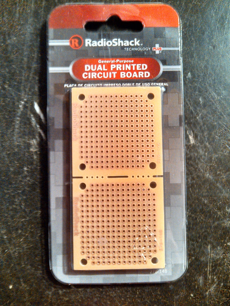
A PC Board (RadioShack- $2.49)
Assorted Wire. (Depending on how far away you want the sensor to be)
Small Speaker (anything should work)
Solder
Card Box (optional)
Some spray paint
Zip Ties (optional)
An LED of your choosing
Tools:
Wire Strippers
A Small Saw
A Drill or Drill Press
A computer and Arduino USB cable
Soldering iron
Step 2: The PIR Sensor


First, we are going to put together the motion Sensor! So go ahead and open up the sensor and the printed circuit board. I cut mine in half since I didn't need the whole thing and could use the other half for other projects.
Once you have both out of the packages, position the three pins from the sensor onto the PCB. Look at the picture to help you. Once you have it positioned on the front row, go ahead and solder it to the board. Make sure you solder on the side with the metal pads, not the blank side.
Once you have it soldered on completely, look closely at the pins. Above them it should say "VCC" "GND" and "OUT". The VCC is where you plug in the +5V the GND goes to ground and the OUT will go to digital pin 7 on the Arduino.
Next, solder three wires right behind where you soldered the three pins just like in the picture. On the bottom of the board you should have 6 solder points. This needs to turn into 3. Connect each pin to a wire you just soldered. The picture explains better than I do. Make sure the wires you solder on are long enough to position the sensor where you want, whether that is right next to you or all the way across the room.
Step 3: Arduino


Next, we need to set up the Arduino. First, the wire connections. Connect the wire that goes to the sensor's GND to the ground on the Arduino. Now connect the VCC to the +5V on the Arduino. Last, connect the OUT to pin #7.
At this time you can also grab the LED and speaker you've retrieved. Connect the + of the speaker to pin #9 and the - to ground. Next, connect the long leg of the LED to pin #13 and the shorter one to the ground right next to pin #13.
Now for the Arduino sketch. You can copy and paste the following into your Arduino IDE:
/* Motion Sensor Sketch by Tommy Hill (tommythehill@gmail.com)
VCC connected to +5V
GND connected to ground
OUT connected to digital pin 7
*/
int outpin = 7;
int led = 13;
void setup() {
pinMode(led, OUTPUT);
pinMode(outpin, INPUT);
pinMode(9, OUTPUT);
}
void loop ()
{
if (digitalRead(outpin) == LOW)
{
digitalWrite(led, LOW);
}
if (digitalRead(outpin) == HIGH)
{
digitalWrite(led, HIGH);
beep(50);
}
}
void beep(unsigned char delayms){
analogWrite(9, 20); // Almost any value can be used except 0 and 255
// experiment to get the best tone
delay(delayms); // wait for a delayms ms
analogWrite(9, 0); // 0 turns it off
delay(delayms); // wait for a delayms ms
}
Upload this sketch to your board and plug your Arduino in! If you have the speaker, LED, and sensor connected properly, you should see a light and hear some buzzing. This is normal even if there isn't any motion. For about 15 seconds when you turn it on, the PIR Sensor has to calibrate and it makes the buzzer go off.
Step 4: The Enclosure
If you don't want to put it in a box, that's okay and you are finished! Congratulations!
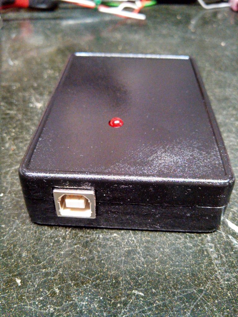
For those of you who want something a little more flashy than a Arduino sitting on your desk, you don't need much to make it look better. All you need is a plastic card box, and a can of spray paint.
First, cut all of the spaces needed to let all of the wires and things out and in. You will need one hole in the back for the wires to the speaker, and the sensor. You will need one hole in the top for the LED, and one last hole on the front for the USB cable to power the Arduino.
After all the holes are cut, paint the enclosure whatever color you want to make it look nice.
Now, close your enclosure up and pat yourself on the back. You are done! Hooray! Now you won't be scared when someone sneaks up behind you, because you will be alerted by the alarm! Thank you so much for reading this. It really means a lot to me. If you liked this, please vote for this Instructable!

Participated in the
Epilog Challenge V

Participated in the
Kit Contest

Participated in the
Pocket Sized Electronics

Participated in the
DIY Soundhack Contest


