

Introduction: DIY Multimedia LED Projector (video Manual)


In this Instructable, I show you how to make a LCD projector with a LED as the light source. I tried to make videos of everything so it is easier to follow the steps.
Este Instructable esta en versión en Español
See more cool projects on my blog.
After making my first LED projector that you can see here , I had lots of questions and people interested in the projector. Some of them went ahead and did something similar like mcastles.
I felt sorry that I could not give more details of the making of the projector. Also the MP4 player that I used is not longer available so many people could not find an MP4 with composite input like mine. I decided to make another one, so you could actually SEE how to do it.
This type of projector is very energy efficient. It only consumes about 41W. A normal projector with metal halide lamp will consume about 260W plus a DVD player which can consume between 20w and 45W for a total of about 300w. That is a saving of a lot of money by the end of the year. Although the quality and brightness of a conventional projector will be better, you'll have to pay the price, and the environment as well.
Another good feature of this projector is that the LED should last about 10000 hours of use wile a conventional projector lamp lasts about 2000 hours.
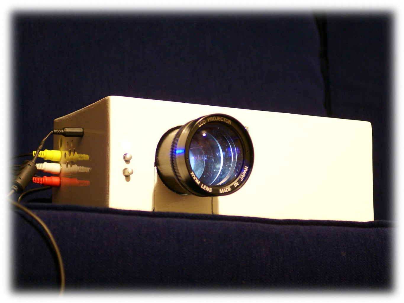
Lets see the result of making this projector.
Step 1: The Principle

The principle is very simple. There is a powerful light that is projected through an LCD into a lens so the image is projected.
Some things you want to take into consideration:
-The better the quality on the LCD, the better the projected image. (I'm using a LCD with 640X480 pixels)
-The LCD can't take more than 40C, so if you decide to use some other type of light source, pay good attention to the cooling system.
-Without a good fresnel lens will be really difficult to light the LCD evenly. (I'm using the always faithful fresnel lens from an old OHP)
-The fresnel from the OHP is really a twin fresnel, the one that faces the light is expanding the light to the full area of the lens, the other one is focusing all the light to one point. If you keep the two of them together (like this projector) it will be a lot easier and less danger of damaging or scratching them. Any big scratch will be reflected in the projected image. The down bit is that you won't be able to do keystoning adjustment. So the projector will have to be placed in a perpendicular position with the screen.
-The use of mirrors allows you to make the box smaller as if there are no mirrors, you will have to place the LED farther from the fresnel lens, and also the LCD from the main lens.
-You need to have everything inside some sort of enclosure, or the light will be coming out and it will light the room making the projector a lot less efficient.
Step 2: Materials and Tools
Here is a list of material I've used to make this projector. Also a list of the tools I've used.
MATERIAL :
-LCD Screen (640x480, view)
-30W High power led (1.8A 16V, view)
-Thermal paste grease (This is to conduct more heat between the LED and the heat sink, view)
-Two Heat sinks. (One for the LED, and the other one to cool the voltage regulator)
-OHP Mirror.
-OHP Fresnel lens.
-Old LCD Projector Lens (If you're using a LCD bigger than 2" you won't be able to use a slide projector lens. I found the LCD projector on the street without light. Some copy lenses are good for this project)
-Some sort of case (I made mine with wood and plywood, but be creative, If you can fit everything inside some sort of metal box, that'll be even smaller.)
-40mm fan ( I took mine from a Mac case I found on the street.)
-20V Laptop charger (4.5A)
-12v PC Speakers
-4 Small washers.
- Paint (only if you decide to paint the enclosure)
ELECTRONICS :
-LM350 (3A Voltage regulator. Used to power the LED, view, datasheet)
-12V Fixed voltage regulator (2A, view, datasheet)
-5V Fixed voltage regulator (2A, This one is not totally necessary, I used it to make the fan less noisy, view, datasheet)
-560 Ohm Resistor
-(2) 1N4001 Diodes
- 0.1 uf Capacitor
- (2) 10 uf Capacitor
- 100nF Capacitor
- 5k variable resistor
TOOLS :
-Drill
-Dremel with cutting disk and round file tool.
-Hole saw.
-Solder.
-Small round file.
-Pliers.
-Double size tape.
-Masking tape.
-Epoxy
ABOUT THE COST...
Step 3: Placing the LED in the Heat Sink


The High Power LED needs to be placed on a Heat sink. The heat sink I'm using is not as big as I would like, that's why I added a fan to cool off the heat sink.
1.- Mark the holes where you'll fix the LED.
2.- Make the holes with the drill.
3.- Put some thermal paste grease.
4.- Fix the LED to the Heat sink.
5.- Find a way to fix the condenser lens later. ( I used some slide lens adapter that I had hanging around. You could use any plastic tube. Make the necessary holes for the cables)
6.- Solder the cables to the LED (Protect the LED before soldering. Pay good attention to the polarity, It should say it)
Here is the video of how I've done it.
Step 4: Mounting the Condenser Lens

The condenser lens will help to project the light further and also will help to avoid loss of light.
1.- The condenser lens I used is from a car, so it has some sort of border around. I used some rigid copper wire to hold it in place.
2.- Use some electrical tape to hold the condenser lens to whatever you're going to use to separate it from the LED.
3.- Use the pliers and some more copper wire to fix the lens to the heat sink.
4.- Give it a try with your bench power supply (Don't have one yet? See here to make your own)
Here is the video of how I've done it.
Step 5: Dismanteling the LCD


Before taking apart the LCD:
-Try the screen and see if it works.
-Don't take the protective film off the LCD. That will be the VERY last step (as it will protect the LCD from scratches).
-Put some tape on top of the protective film and write down some letters (like DVD). This will help you always see what is the top and bottom of the LCD, even without having to turn it on.
A picture is worth a thousand words... so I guess a video is worth even more..... so.... Here is the video of how to take apart and desolder the back light.
I tried to do everything in front of the camera, but some times I forgot, sorry! :)
And here the video of how to desolder the backlight.
Step 6: LCD Mount

A good and easy way to mount the LCD is to use the same case where it goes.
1.- File a little bit the with the dremel the 4 holding points where the circuit was screwed to the casing. (This is done so you can fix the LCD with some washers as you can see in the video)
2.- Place the LCD with the wires at the top.
3.- Use the same screws that used to hold the circuit with a few washers to hold the LCD in place.
Step 7: PCB Fitting

This is very important, as placing the LCD circuit near the LCD without blocking the LCD itself is vital for a good result.
1.- Place the circuit on top of the plastic that is holding the LCD and mark the two holes where the circuit will be fitted.
2.- File the holes a little bit until you can fix the screws you want to use. If you can take out of a old computer the type of screw I'm using (they are called standoffs screws), it would be better as these screws still separate the circuit from the case a little bit.
3.- Drill the case and, after protecting the LCD, use some epoxy to glue the screws.
4.- Fix the cables to something so you wont break it. I used a cable tie.
Step 8: Schematic


Here is the schematic. Place the voltage regulator in a good heat sink.
With the LM350 I can change the voltage with the 5k variable resistor and at the same time I have the ammeter connected to make sure the amps will not raise 1.7A. (The LED is rated 1.8A but just to be on the safe side)
PLEASE NOTE : I found a problem on the schematics, there shouldn't be connection between the anode of the 1n4001 and the negative of the 10uf.
Step 9: LCD Stand

From now on we are going to make everything able to stand in an upright position. This is going to allow us to play with the distances of everything to get the picture right.
The first thing we'll be getting in an upright position is the LCD as it's the main point to get the other things lined up.
1.- I found some heat sink supports from an old amplifier. But you can use anything in a right angle.
2.- Mark where they'll go (Pay attention that they will not block any light.)
3.- Drill the case and screw to it.
It is very important now that you are able to get the LCD in a straight position by measuring from the middle of the LCD to the holding surface. This measurement will have to be the same for the light source (LED with condenser lens) and the main projection lens.
Step 10: Fit Legs to the Light Source

Now that we know the height of the centre of the LCD, we need to make everything line up with that. So the first thing is the light source.
1.- I found some plastic legs that will do the job, but you could even use some wood cut to size.
2.- Drill the heat sink where you think it will be a good place to fitted.
Step 11: The Mirrors

The mirrors came from the mirror of an OHP.
1.- Protect the mirror with some masking tape.
2.- Mark the centre of the mirror and take it to your local glaziers to get it cut. (normally they wont charge for such a small job)
3.- I found a couple of angle metal things, and with some double sided tape I held the mirror to it. (This will be provisional, as once you know the right position of the mirrors you can reinforce it with some hot glue.)
Step 12: The Projector Lens

I was really lucky, because the projector lens I'm using has some sort of metal support, and the height was almost exactly with the centre of the LCD. All I had to do was drill a couple of holes to fit it to the wood.
Step 13: Cutting the Fresnel Lens


When cutting the fresnel lens you could use many tools. I decided to use the angle grinder to be quicker, but this is not a toy, is very dangerous if you don't know how to use it. You should wear a mask (the fumes from the fresnel when cutting aren't very healthy), safety glasses and gloves. But you could cut the fresnel with a dremel or some other thing.
1.- Mark the centre of the fresnel. (see the video to know how to)
2.- Use some masking tape to protect the fresnel as any big marks on the fresnel will be visible on the projected image.
3.- Now that we know the centre of the LCD, we want to do the same on the fresnel. So measure the space from the base of the projector and the circuit, paying good attention to the center (see the video to know what I mean. Do your best, if its not right right on the center is still ok)
4.- After cutting the fresnel, tape the borders to stop the fresnel coming apart, or dust getting in between them.
Step 14: Work Out the Distances


We now have everything ready to work out the distances This really depends on your personal setting of the condenser lens, LCD, mirrors, lenses... etc..
- The best thing to do is play with the distances and mark everything once you're happy with the result.
- Try the distances where you will think the projector is going to be. Some lenses wont focus from too far and too close.
This is my setting. I used two mirrors to keep the enclosure as small as possible.
Step 15: The AV Connectors


I recycled the AV connectors. If you are doing the same:
1.- Cut the circuit board with some scissors, or with the dremel.
2.- Make sure the lines on the circuit board are cut.
3.- Solder the cables
4.- Hold the cables with a cable tie.
Step 16: The Box


My box is made of wood and plywood. I made it to fix the top to the base, so they will be no screws showing in the sides.
1.- Before making the enclosure, take measures of the height of everything, and mark them so you don't place something where it will be in the way.
2.- Once you have the enclosure ready, cut and drill all the holes needed for the sound system, buttons, speakers, connectors, fan, etc.... Also make a few holes under the heat sink of the LED to allow air flow.
3.- Use some two part filler If you're using plywood and want to make it smooth.
4.- Paint the enclosure. The way I painted mine was with a couple of coats of oil based primer and then with another couple of coats of oil base paint. (it took forever, with this cold I had to wait around 12h between coats)
5.- Is a good idea to fit a couple of small legs at the bottom, and some sort of leg at the front that can make the front of the projector go up and down. I used a leg with that feature, but if you don't have anything like that you could always use a screw.
6.- Paint the base in matt black so they will be no reflections. I use some black shoe polish, and it did work well.
Step 17: Sound System


My sound system came from the computer speaker. If they work at 12v even better as you need to drop down the voltage to 12v for the LCD.
1.- Take it apart.
2.- I modified the circuit so I could use the sound system switch as main switch. see pics
3.- Later I change the LED of the sound circuit for a blue LED, which looks cooler!
Step 18: Power Connector


I fitted the power connector once I knew where it could go.
1.- Mark where the power connector can go from the inside.
2.- Use a needle or a small nail to make a small hole from the inside out.
3.- Drill the hole for the connector.
Step 19: Hot Glue


Now you can hot glue everything to the case. Wait until the glue is fully dry before closing the case.
Step 20: USB Multimedia Reader


Here are a few pictures of the multimedia player. I had a portable DVD player that din't want to read DVD's any more so I took it apart and place it inside the projector.
Step 21: Finishing Touches


Everything seems to be working ok, you're happy with the projector, but maybe there is some light coming out of the box. Use some foam like in the video to cover around the lens and other areas where some light is coming out.
I also place a few labels with some rub-on letters like you can see in the pictures.
Step 22: You're Done!

Well done! You were able to make your own projector with an LED, which will last almost forever.
Now relax on the sofa while you watch your favourite movie on a 2m diagonal screen. (by the way, for the screen I'm using an Ikea roller blind, works GREAT!)
I hope you like this Instructable, I did work hard to make it as good as I can, but maybe I missed a step or something, so just ask if you have any questions.
Step 23: Cleaning the Projector

After some time using the projector you may see that there is small marks or dust on the projected image. That is normal, the LCD could get some dust or something that needs to be cleaned from time to time (not very often though)
First take the lid off your projector. Here is a video of how to do it if you have a enclosure like mine.
To clean the projector you could use a blower cleaner. I use this blower that is to clean my camera. It only takes a minute.


