

Introduction: DIY Paper Tape/Punch Card Maker and Reader


Paper tape and punch cards were used back in the 1950's and 60's (and even as late as the 1990s) as data storage for various computers and even CNC machines! To hand cut or to hand read the card would be terribly time-consuming so why not just make your own!
Needed:
- Parallax Propeller Activity Board (or MCU of your choice)
- Silhouette Portrait
- Bandsaw
- Table Saw
- Drill Press
- Glue
- Nail/Hammer
For the Paper Tape/Punch Card reader head:
- Scrap Ribbon Cable
- Wires
- 2x 1x10 male header
- Scrap Wood
- 10x photoresistors
- 10x 3mm white LEDs
- Perf board
- Soldering Iron/Solder
- Wire Strippers
- 100 ohm resistor
For the Paper Tape:
- Old Folder (not manila or transparent)
- Scissors
Step 1: Create the LED Reader


Solder the 10 photoresistors to a piece of perfboard. The perfboard we used consisted of 2x 2x20 columns with horizontal electrical connections. Solder the photoresistors between these two columns - though if you set up the electrical connections, you can use any kind of perfboard.
One one side, bend one lead of each photoresistor to connect to its neighbor and solder them together. Trim any extra pieces off. This side will be connected to Vcc (3.3V) eventually.
Step 2: Solder the LED Reader to a Header


Take a piece of ribbon cable with 10 lines and about 6-10" in length, and strip about 3mm on both ends and tin them. Solder these to a 1x10 pin male header.
The first 9 wires from the header should be soldered in order to the perfboard. Make sure to solder them on the side where the photoresistors are NOT connected to each other. And make sure the wires are coming out from below the perfboard, away from the photoresistors.
The last wire will provide power to the photoresistors. Solder this to the other side of the photoresistors, opposite of the wires you just soldered.
Step 3: Create the LED Bar


Using another piece of perfboard, place the LEDs in the same spacing as the cadmium cells. You want to make sure that the polarity of each LED is the same as the next. Using the same method as before, take the leads of the LEDs, bend them over to touch the lead of the LED next to them, and solder them together.
Do this for both sides. One side will connect to GND and one side will connected to 5V. Do not, however, test these lights without a current limiting resistor!
Take ribbon cable and solder one wire to one rail/side of the LED perf board, and solder another wire to the other side. On the end of this ribbon cable, solder a 1x2 pin male header.
Step 4: Set-up the Chassis for Paper Tape Reader


Look through your scrap wood! I found a black walnut piece that was roughly twice the height of the LEDs off of the board and wide enough for ~1.5cm clearance on either side of the perfboard.
Using a spare header, mark out where the leds are. This will serve as a template for where you need to drill the holes for the LEDs. Mark where you will need to drill on the wood.
Step 5: Drill the Holes for the Chassis


Use a tap (nail and hammer) to mark where your drill bit will drill through the piece of wood. This helps to keep the drill bit from drifting when you first start drilling.
Choose an appropriately sized drill bit which will allow the LED to fit snugly in.
Drill the holes all the way through the piece of wood.
Step 6: Cut the Piece of Wood in Half


Using a sturdy guide and your bandsaw, cut the piece of wood you just drilled into two halves (or slices). This will take a little bit of time depending on the type of wood you've chosen.
Once the two halves have been cut, sand to get rid of any large imperfections.
You can now testfit the LEDs into the holes you've just drilled. One half of the chassis is now complete!
Step 7: Set Up the Wood Piece for the Photoresistors


Using a table saw, carefully route a 1/16" slot into one side of the wooden board. This slot is where the paper tape goes through. We made this slot width 2.25" wide, but if you want to create wider paper tape, you are welcome to do so. The way our table saw blade cuts, we made it a ridged slot, but you are welcome to make it a flat surface.
Then, turn this board 90 degrees, and cut out a 1/16" slot for the photoresistors to fit in. The width of the slot will be the width of a photoresistor. You do not want too much play for the photoresistors to move, and you want to make sure the slot is cut where the holes are. This will keep the distance between LED and photoresistor short, to prevent light bleed from other LEDs!
In the last photo, you can see the slot and clamping to ensure that all of the pieces fit together.
Step 8: Create the Resistor Network


Take a 1x10 pin male header and solder 9 10k ohm resistors - one to each pin. Take the other lead of each resistor and bend it over to the next resistor. The last resistor is soldered to the 10th pin. This will eventually be connected to GND.
Step 9: Connect the LED Reader Portions on the Breadboard


The great thing about Parallax Propeller boards are that they have small breadboarding spots. Please refer to the diagram to see where the connections should go.
You will need wires to go from the various headers to the pins, and to the appropiate VCC/GND points. For the LED bar, you will need at least a 100ohm resistor to act as a current limiting resistor, otherwise at 5V, you WILL overdrive the LEDs and risk having to resolder them!
Step 10: Glue Up the Hardware!


This step can theoretically be done at the end after you've tested the code, but in case you'd like to be done with the hardware portion, here it is!
Glue up the two halves of the wooden reader. Remember to only put glue on the ends, and not inside the slot since the paper tape needs to go through that slot!
Once that has cured, take a look at the gap between the perfboard and your wooden reader when the photoresistors are seated in the slot. My perfboard and the wooden reader happened to be separated by the the height of a PCB. So I took small bits of a scrap pcb and using pro-bond, glued it to the ends of the perfboard.
Once that has cured, place glue on the little scrap pcbs and clamp that to the wooden reader. Make sure to not get any glue on the photoresistors lest you block light!
Your set up should roughly look like the one in the last photo for this step.
Step 11: Program the Propeller
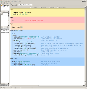
Now that you have the hardware set up, program the Propeller's eeprom with the following code. What this does is show you what letters your punch card/paper tape represent - so you know what the message is! I will show what you will see at the end!
Code: http://pastebin.com/D9ZdHQsg
Step 12: Creating Your Paper Tape!


We are finally to the point where we can create our paper tape!
Take an older folder you may have lying around and have no use for. Cut it so that it's a useable rectangle/square. Affix it to the Silhouette cutting backer, and load into the Silhouette Portrait with the top right button.
We threw a quick program together (instead of laying the message out by hand in a graphics editor) which would allow you to write whatever message we wanted. This paper tape reader uses ASCII bit representation, so it can support odd symbols as well as your typical A,B,C.
With the program, we had it save out to a bmp which we could then upload to Silhouette Studio.
Note, when you make your graphic, make sure the index pulse (a pulse that is on all of the time to let the system know when to read the line), consists of smaller holes than what your data is represented by. This helps prevent false-positives.
Step 13: Print the Paper Tape/punch Card


Using Silhouette Studio, set your graphic up for printing. I had to resize the document in Silhouette Studio to a height of 2.037", and an overall border that had a 2.117" height. This will be different depending on the width of your board and on the size of your holes and how they match the holes you've drilled.
Easiest way I did this was by printing out different tape sizes and looking to see which ones matched the best. This portion may be the most time intensive but is the most important for ensuring the data you're sending to the serial terminal is correctly read.
Set the Silhouette cutting setting to cut cardstock with a speed of 4, thickness of 33, and allow for double cutting. Now, send to printer and wait!
You will see the following! (note picture 3)
Step 14: Clean Up the Paper Tape


Clean up time! Take your cut piece off of the backing and start cleaning out the holes! Ideally, most of them should come out fairly easily, but there may be occasionally "hanging chads" that you need to get rid of. I used a small screwdriver to help in the process.
Confetti for everyone! Data for me :).
Step 15: Test, Run, and Use!


Now that you have everything wired up, you have the reader ready - turn on your Parallax Propeller board. The LEDs should all light up. Remember that the led that is farther from the others should be matched with the index pulse. If you are seeing odd messages, make sure that your header from the photoresistors is plugged in, in the correct direction.
In any case, enable the serial terminal and run the card through!
Looks like our message for this card is....
Hello, World! Testing 12345. ASCII
Now, you can create longer messages by making actual tape or combining multiple punch cards, or keep it nice and short and treat this reader like a card reader! Enjoy!


