

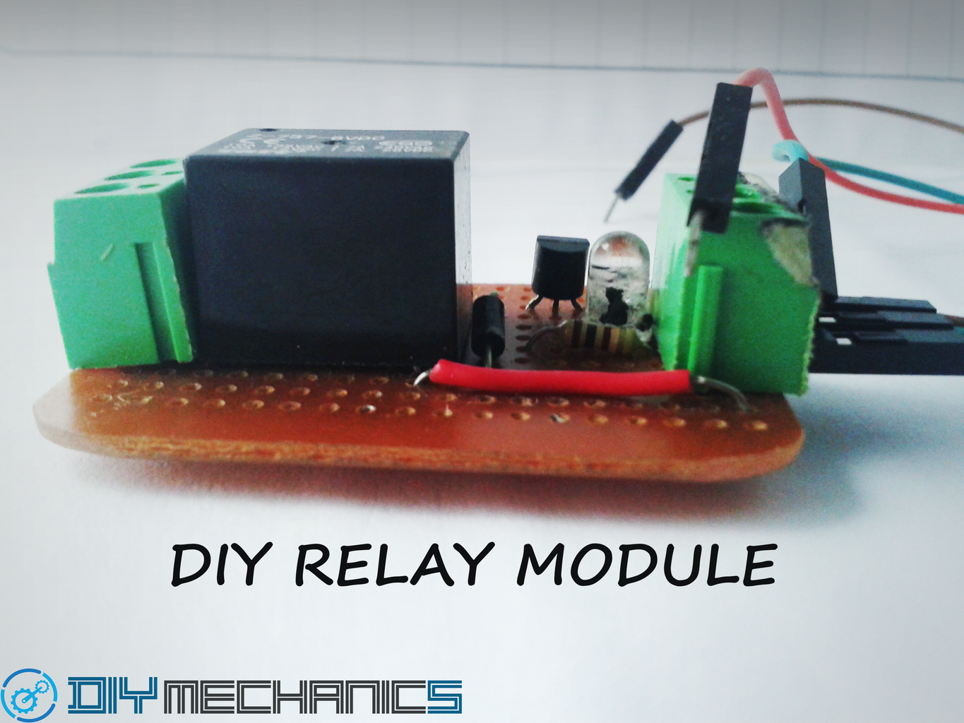
Introduction: DIY RELAY MODULE


Hi guys how are you ?
I hope you are fine !
Are you looking for making a relay board yourself , then your in right place.
today i will show you how to make a Diy relay module
that can be used any purpose . Even you can hookup with your Arduino or raspberry pi else use it for any project you needed a relay module. It costed me about 1$ (USD) to make one.
The reason i come up with this tutorial is last week i needed to make a project so fast(its a urgent project for my college) i needed a relay module to finish the last stage of the project, unfortunately i screwed . there is no relay module left in my garage . So, i went to a local store to buy one but there is no 5 volt or 6 volt relay module.But fortunately they have the relays , i bought so many(hope i can use like this situation in future :D) .then made one myself.
Its cheap and easy , you can save a little bit money by making these Diy relay module . At the same time you can use this relay module like a ordinary relay module. I made a single channel but you can make more on a same PCB.
for multiple channel like 2 or more , make copies of the same circuit in a single PCB.
So lets start making guys....!!!!
Step 1: COLLECT THE PARTS


Now we need to collect some parts that we needed to make the Diy relay module.
NOTE : Most of the parts was lying around my home,I used to save little more ¢
here the list of all the parts you needed to do this project:
HARDWARE:
1. 5 volt relay(i used 6 volt because i need 6 volt relay)
2. BC548 transistor.
3. 100ohms resistor.
4. IN4001diode.
5. Screw terminals(3 pols , 2 nos)
6. LED(red or green,i used green here)
7. "5x3"cm Copper clad(optional if using general purpose PCB)
8. General purpose PCB(optional if use copper clad).
9. Breadboard and Jumpers.
SOFTWARE:
1. Fritzing
GENERAL TOOLS:
1. Soldering iorn.
2. Soldering wire.
3. Soldering paste(optional,but recommended).
4. Hookup wire.
if you have any doubt in parts see the pictures above to clear the doubts or comment .
Step 2: TESTING ON BREADBOARD


Now we have all the parts to make a Diy relay module.
Now we need to test the circuit diagram of the relay module on a breadboard.
don't skip this step , it is necessary to avoid mistakes when soldering into a PCB and check if it is works.
After all parts you collected lets go ahead to the next step.
Take a look the schematic diagram and PCB layouts.Then wire the circuit on a breadboard.Double check the schematics diagrams and Breadboard wiring for any wrong connection.
I gave the Pinouts diagram of BC548 transistor. carefull for wrong connections.
Now we need to check if it is working:
- first download the relay.ino file then open with your Arduino.
- connect the Vcc and GND pins of the relay module to the Arduino's 5 volt pin and gnd pin.
- then connect the relays input pin(the pin comes from the transistor's base pin) to the Arduino's digital pin 13.
- then upload the code.
- and check the relay is turning ON and OFF in a 1 second intervals(also the LED of relay module will turn ON and OFF)
if it is note working, suddenly turn OFF the Arduino .then check for any wrong connection existing,if have then solve that and re power the Arduino.
wooooww!!!!!! its works . Now we need to make the circuit on a General purpose pcb or custom pcb.

Step 3: DIY RELAY MODULE ON GENERAL PURPOSE PCB(optional).


Now the time for make the circuit on a general PCB or a custom PCB.
this step is optional if you are decided to make the module on a custom PCB.
I really recommend make a custom pcb because it is more professional and perfect one.
However its your wish which way you need to make.
Here i will explain how to make the module on a general purpose PCB!.
- First take a general purpose PCB then clean well.
- After cleaning then rub some flux on it(optional,but recommended)
- them mount the components on the PCB then solder it.
- After solder everything then complete all traces(connections)using a Hookup wire.
YES!!!!!!!
We made the Diy relay module on a general purpose PCB.
Now check the relay works.
I EXPLAINED IT BEFORE THIS STEP (STEP 2)!
So, if you are like to make a custom PCB , we can go to the next step.
Step 4: DIY RELAY MODULE ON CUSTOM PCB(optional)
This step is optional if you made the module on a general purpose PCB!
I really recommend the Custom PCB,because the custom PCB is more clean and professional and less chance to short circuit.
i'am not made on custom pcb because i don't have time to make the PCB i said the situation before.
However lets go and make the PCB first!
watch the below video for how to etch a PCB yourself using toner transfer method.
After completing the video tutorial .
Download the fritzing project file down below( PCB design)
Then open the fritzing software(if not download and installed click here )
If you don't know how to use fritzing , click here(complete the tutorial , it almost three parts)
Then do the same you learned from the PCB ETCHING tutorial.
After etch the PCB . use a 0.8mm or 1.0mm drill bits to drill the holes in the PCB.
Then mount all the components and solder it.
DONE!
we made the custom PCB for Diy relay module.
Now test the module.
I'am explained before in the step 2!
Attachments
Step 5: DONE !!!
We successfully made our Diy relay module.
It would take me up to 20 minuites to make one . This is easy , inexpensive , cheap and also time saving(when you order one from online,take minimum a day) .
If you made one please click on I MADE IT button and also post the photo of your finished Diy relay module in comment section.


