

Introduction: DIY Servo Motor
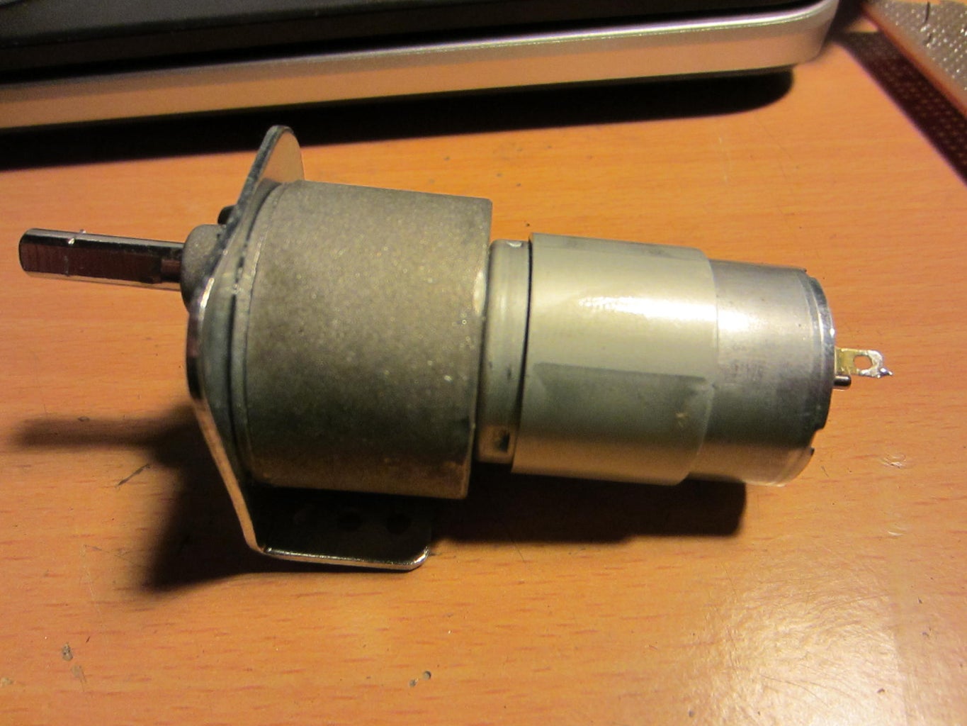


DC Motors can be made to turn either clockwise or counter-clockwise by changing the polarity of the voltage applied to their terminals. The torque that is generated at the output shaft can be scaled up or scaled down by using a gear train. In most motors, like the one shown below, the gear train scales up the torque of the motor by using a reduction gearing that outputs a much higher torque (albeit at the cost of a much reduced output RPM).
The problem with DC motors is that when they have a voltage applied to their terminals, they tend to rotate forever in a particular direction, stopping or reversing the motor can only be achieved by cutting off electric supply or reversing polarity. In a DC Motor, speed control can be achieved by varying the terminal voltage but position control of the shaft is very difficult to implement.
Servo motors on the other hand, allow us to control the position (or angle) of the motor output shaft. This can be very useful when we want to move a control surface such as a rudder or a thruster to a particular position.
Step 1: Dealing With Cost


Servo motors are expensive. They get more and more expensive as their output torque increases. Digital servos are even more expensive than analog ones and I am not sure that one can even buy servo motors with torques higher than about 30 kgf-cm.
I needed a servo motor that could generate 120 kgf-cm of torque for a robotics application. As you can see from my extrapolated price graph, this type pf servo would have cost me a few hundred dollars!
To get around this, I decided to make my own servo motor using a cheap (under 20$) DC motor and some simple electronics.....
Step 2: How It Works...


In order to control the shaft position of a DC motor (and thereby convert it into a servo motor), you need to be able to ‘encode’ the position of the shaft. This ‘current position’ will be compared against an ‘desired position’ and a ‘positional error’ will be generated. Voltage applied to the motor terminals will be so as to cause the shaft to turn to reduce ‘positional error’ to zero. This sort of a ‘feedback’ system is also used in commercially available servo motors.
To implement the feedback loop you will need to fix the shaft of a rotary potentiometer to the foundation of the motor while allowing the potentiometer’s body to rotate freely with the motor shaft. This arrangement is known as a shaft encoder. Now, as the motor shaftrotates , there will be a corresponding angular movement between the potentiometer shaft and its body. By sensing the voltage at the wiper terminal of the potentiometer, you can measure the angular position of the motor shaft. This angle will then be fed into the feedback loop allowing software on a microcontroller to control the angular position of the motor shaft.
Step 3: Circuit Diagram


I used Fritzing to create the circuit diagram for my DIY servo motor. You can download the circuit by clicking the link below.
To be able to turn the motor shaft in both directions, you will need to use a H-bridge IC like an L293N. Any microcontroller can be used to control the servo, in the circuit above, I use an Arduino Mega.
Attachments

Step 4: Code
Download the arduino sketch (customServo.ino) that controls the motor using the links below. Within the code is the c++ class DCMotor. This class has a member function GoToAngle(i,j) where 'i' is the desired angle of the shaft and 'j' is the turning speed of the motor. You can call GoToAngle() repeatedly or whenever required to bring the motor shaft to any desired angle. The code is heavily commented at every step so that it is easy to read.
The embedded video demonstrates the whole build process. The code shown in the video is of a slightly older version and is not the same as contained in customServo.ino


