

Introduction: DIY Seven Segment Display 2ʺ


This display can be built as either common anode or common cathode. The components for the project are a PCB, 29 LEDs of 3mm, 8 resistors and 2 pass through female headers for arduino 1x6. DIY Seven Segment Display 2ʺ is ideal for arduino projects and design of counters. However, if you design a counter, you should leave free the decimal point pin. See the video at:
http://www.youtube.com/watch?v=Gr38GiUDEik
Step 1: Bill of Materials


1 PCB 1.5ʺ x 3.5ʺ ( Jameco PN: 105102)
29 LED's of 3 mm
8 Resistors of 200 ohm
2 Pass-through female headers for Arduino 1 x 6
Step 2: Project's Diagram


In this project, you have the option of assembling a common anode display or a common cathode display by depending of your needs. Check your LED's before using them. Can use a round battery of 3 Volt.
Attachments

Step 3: Prepare the Segment "a"


Remember that you are going to construct segments of 4 LED's in parallel. That is, you will both connect all anodes and all cathodes by leaving free only an anode and a cathode of your set of 4 LED's. Check the LED's before using them. Next, install the LED's for forming the segment "a" of your display that you decided to do. For example, if you decided to built a common anode display, you need to leave free the cathode for being connected with the resistors while you need to leave free the anode for being connected to the rest of the anodes to construct the famous common anode. You can use the round battery of 3V to check each segment that you do.
Step 4: Prepare the Segment "b"


Check the LED"s before installing them. After constructing the segment "b" of your display, check it again. Remember that you have two terminals in each segment to test easily.
Step 5: Prepare the Segment "f"


Test 4 LED's more before connecting them. Form the segment "f " and check it again.
Step 6: Prepare the Segment "g"


Take 4 LED's more and check them before installing them. Construct the segment " g " and test the segment constructed.
Step 7: Prepare the Segment "c "


Check 4 LED's more before connecting them. Form the segment "c " and test it again.
Step 8: Prepare the Segment "d"


Test 4 LED's more and form the segment " d ". Next, check it if it functions. Remember that you can use a round battery of 3 Volt for checking if segment constructed is functioning correctly.
Step 9: Prepare the Segment "e"


Form the segment "e" by testing the LED's before installing them. Once you assemble the set of LED's, check it again to verify its functionally.
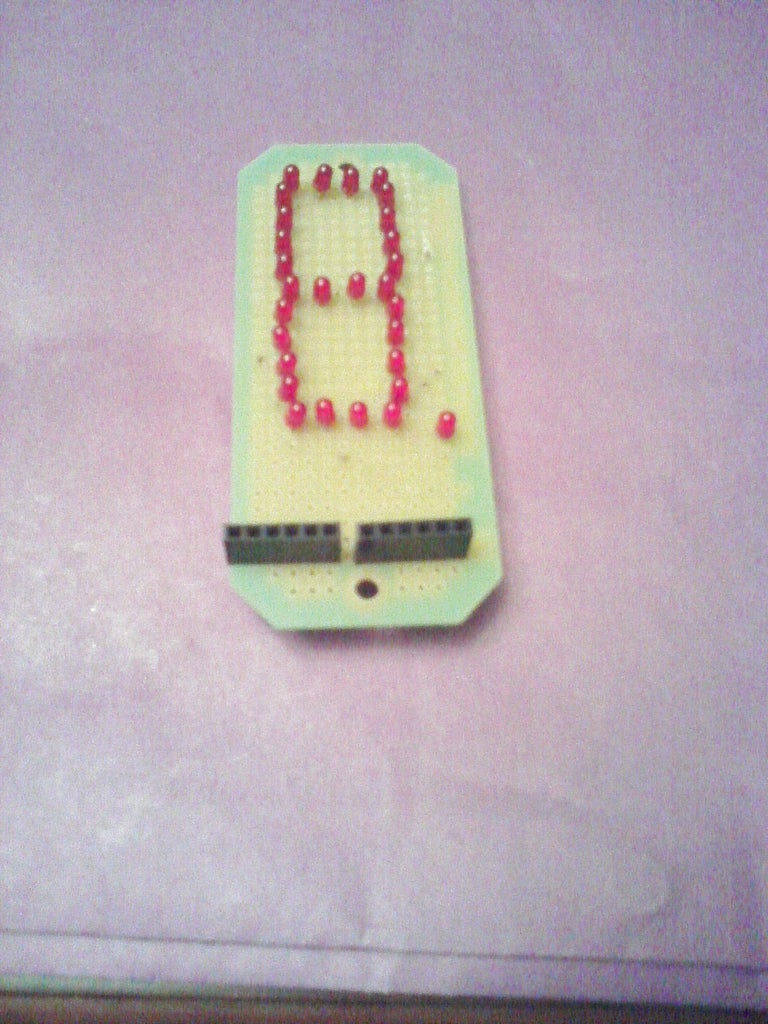
Step 10: Prepare the Decimal Point (dp)


Take the last LED you have for forming the "dp", but test it before and after assembling it.
Step 11: Install the Resistors


Install the resistors of 200 ohm by verifying continuity in your circuit and in the correct track before continuing with the following step of the project.
Step 12: Install One of the Female Headers Pins 1 X 6


Install one of the female headers pins of 1 x 6 and connect the free end of the resistors of the segments from "a" to "e" and common anode (+) by verifying continuity always.
Step 13: Prepare the Other Female Headers Pins 1 X 6


Prepare the other female headers pins 1 X 6 by cutting the pins that you don't need to leave only three pins in your female header. Check the photos.
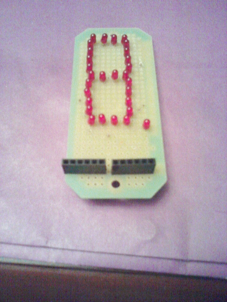
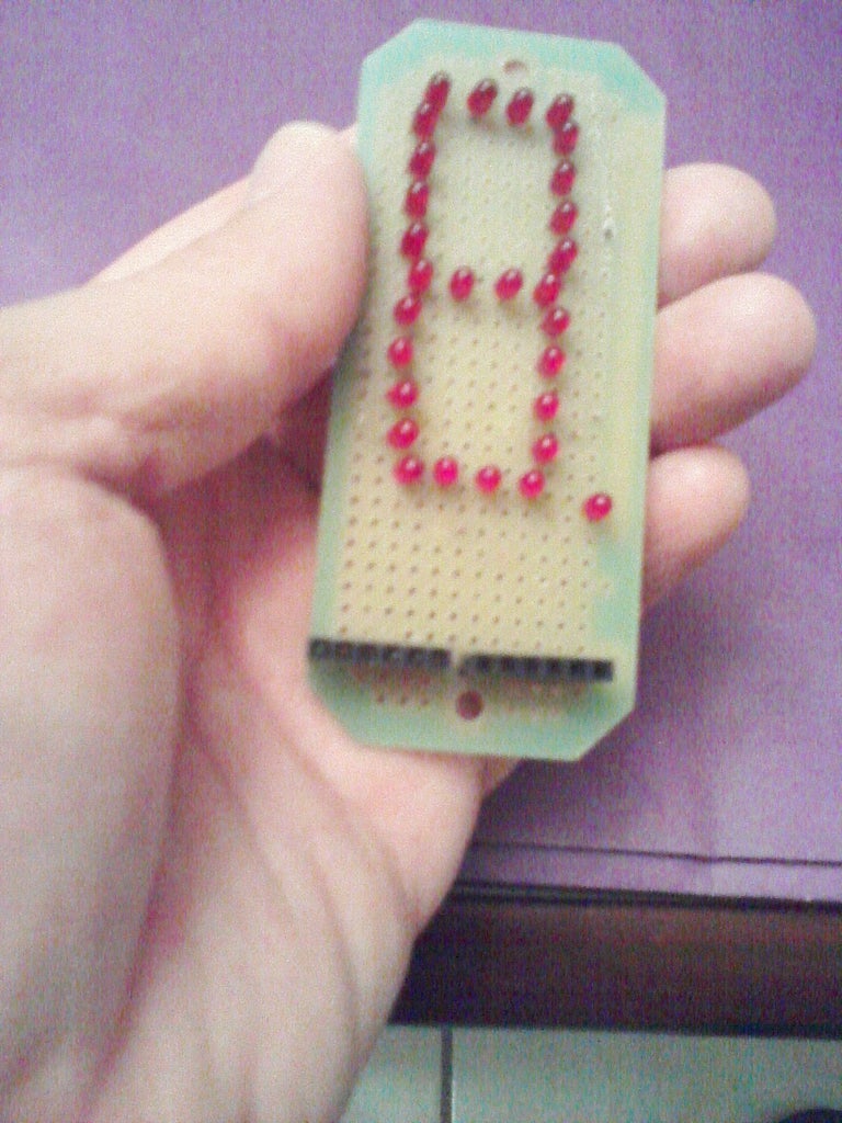
Step 14: Complete Your Project


Complete your project by checking each of the segments of the display by using a power supply of 5 Volt.


