

Introduction: DIY Smart Augmented Reality Glasses Using Arduino


As technology is growing rapidly and integrating itself to all aspects of people’s life, designers and developers tried to provide a more pleasant experience of technology to people. One of the technology trends which aim to make life easier is wearable computing. Wearable’s aim to assist people to be in control of their life by augmenting the real life with extra information constantly and ubiquitously. One of the growing trends of wearable computing is Head Mounted Displays (HMD), as the head is a great gateway to receive audio, visual and hectic information. Also due to the Google Glass project, wearable’s in form of glasses gained much more attention during last year’s. Google Glass is as futuristic a gadget we’ve seen in recent times. A useful technique for all kinds of people including handicapped/disabled.
Inspired by Google glasses, I made a wearable prototype that can function quite similar to Google Glass. In this project, we will make a wearable extension that can work like Google glasses, and it will be used to send notifications of calls and messages received on mobile phones, and also show time and date, all in front of wearer’s eye.
Google Glasses are available in market at price of $1000-$1500. Here we will make this project under, Rs.1000 or $15.
Smart- Glasses are the wearable computing device used as an extension, which can be attached to the spectacles or sunglasses of the wearer, and can be paired with Smart Phones, via Bluetooth. This extension, contains an Arduino Micro-controller having ATmega328p microprocessor, which is programmed to connect with Smart-Phones through a Smart-phone application. A Bluetooth module, named HC-05 is interfaced with ATmega328p, which is used to connect with smart-phones. A battery / Re-chargeable battery of 5V is used as power supply for Smart-Glass. An SSD1306, 0.96” OLED display is interfaced with ATmega328p, which is used to display the data received from Smart-phones. Smart-Phone application is used to transmit data of the phone, i.e; Date, Time, Notifications of Phone call and Text messages.
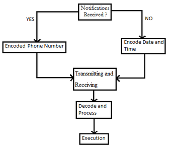
The following are the main steps that are implemented during the whole process:
- Notifications Received.
- Encoding.
- Transmitting and Receiving.
- Decode and Process.
- Execution
The basic principle of this project is to create a working prototype and that too within a very less cost.
Step 1: COMPONENTS REQUIRED :
- Arduino Nano, (ATMega328p)
- Battery ( we have used 9V battery)
- Bluetooth module (HC-05)
- OLED display (SSD1306)
- Wires for connection
- Push Button
- Bluetooth Earphone (LG HBS 760) [This is optional. I had a damaged set, so I used it too.]
- Toggle switch
- Basic Frame ( we made this frame using Sunmica Sheet, by remolding its shape using Solder iron)
Step 2: PROGRAM :
Upload the given program in Arduino Nano. But first, download the library for the program.
For downloading the library, follow these steps; Sketch > Include Library > Manage Library > Search for " SSD1306" and install the Adafruit_SSD1306
Or if the given Arduino program doesn't work, then copy and upload the program given below;
#include <SPI.h>
#include <Wire.h>
#include <Adafruit_GFX.h>
#include <Adafruit_SSD1306.h>
#define OLED_RESET 4
Adafruit_SSD1306 display(OLED_RESET);
void setup() {
Serial.begin(9600);
display.begin(SSD1306_SWITCHCAPVCC, 0x3D);
display.display();
delay(2000);
display.clearDisplay();
}
void loop() {
while(Serial.available() > 0){
String Date = Serial.readStringUntil('|');
Serial.read();
String Time = Serial.readStringUntil('|');
Serial.read();
String Phone = Serial.readStringUntil('|');
Serial.read();
String Text = Serial.readStringUntil('\n');
Serial.read();
}
if(Text == "text" && Phone == "phone")
{ display.println(Date);
display.display();
display.println(Time);
display.display();
display.clearDisplay();
}
if (Text != "text" && Phone == "phone"){
display.println(Text);
display.display();
delay(5000);
display.clearDisplay();
}
if (Text == "text" && Phone != "phone"){
display.println(Phone);
display.display();
delay(5000);
display.clearDisplay();
}
}
Attachments

Step 3: APPLICATION :
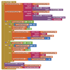
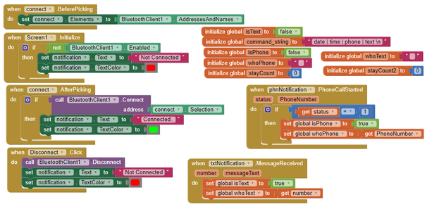
If the given .apk doesn't work, or you want to create your own customized app. Then you can use app inventor website and make the functional blocks as given above.
OR
Download the .apk and install it.
Attachments
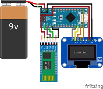
Step 4: CONNECTION :
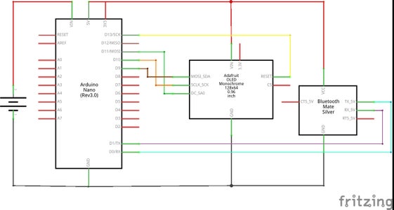
Connect the circuit as shown in this schematic diagram.
Connect to the battery and turn on the supply.
Step 5: SETUP :
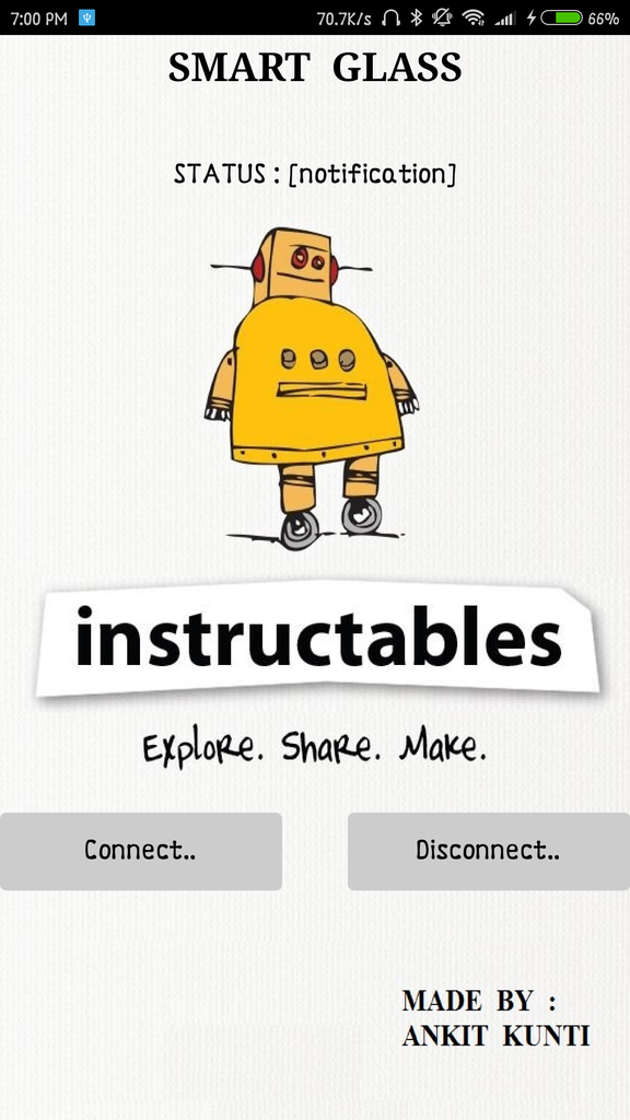
Pair Bluetooth module with phone’s Bluetooth. The App will show the above image.
Step 6: BODY / FRAME WORK :

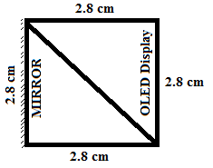
Make the frame as shown in the figure, or as per your choice. I made this frame using plywood Sunmica, by using the soldering iron to make the curve. You can make it as per your design.
For Display, you can use the above template as a reference.
Step 7: RESULT :
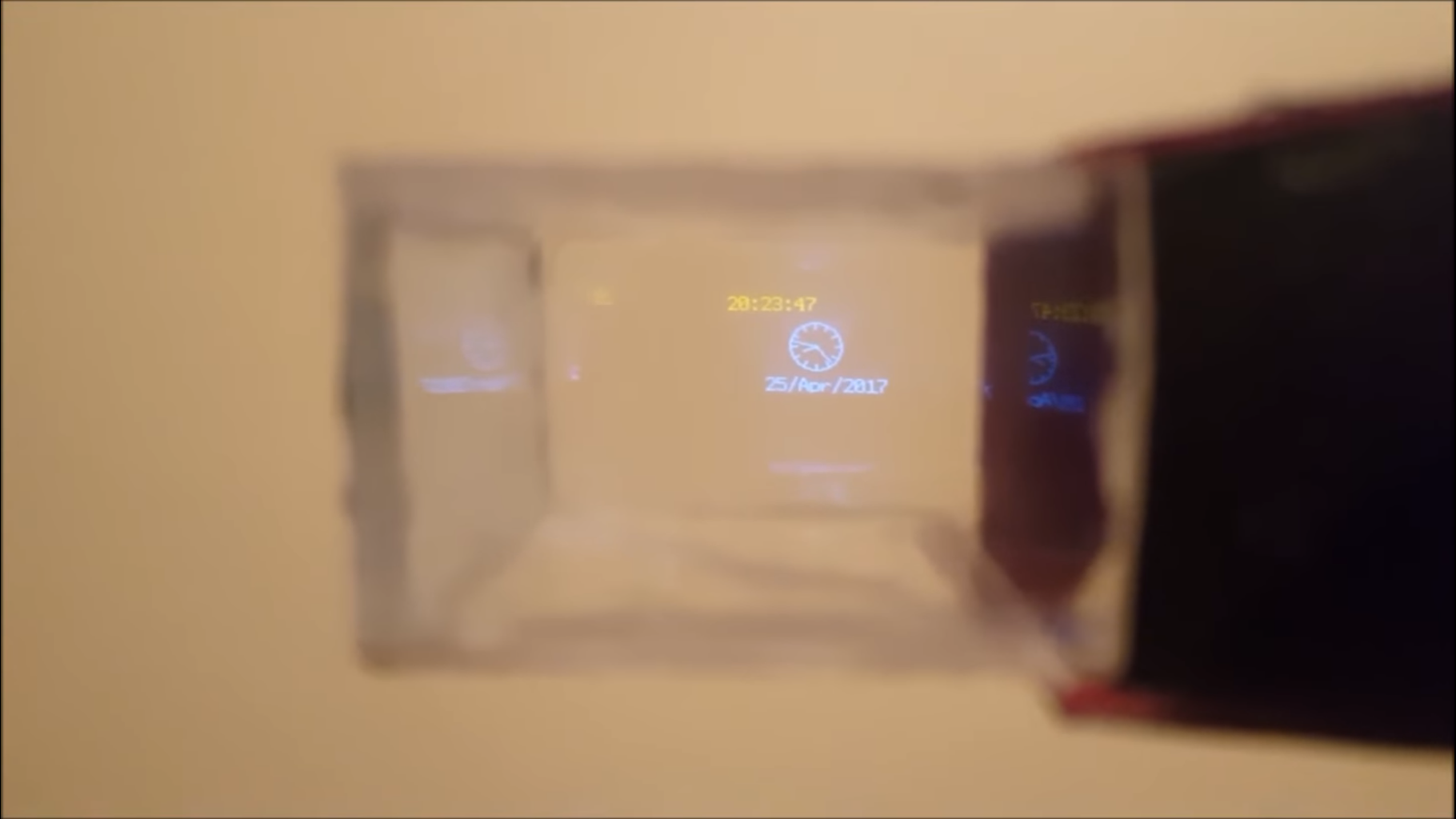
As a result, something similar to the above image will appear on the Display.
If you have any suggestions to make it better, you can comment down.


