

Introduction: DIY Motorized Moving Timelapse Camera Dolly With Arduino


This is my attempt in making a dolly for a camera.Honestly my knowledge on photography is limited but I have friends helping with this part.As far as the building part goes I can handle it.I first saw a moving video time-lapse and fell in love with it so I thought I would give it a try. There were many changes during the construction so I do not have step by step photos but I will do my best.
Step 1: Slider


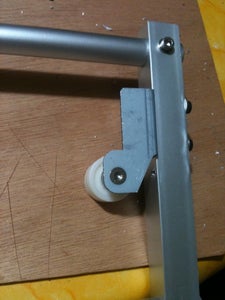


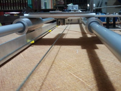
The basic slider consists of two 10mm aluminum tubes about a meter long and two wider tubes sliding over them.I have made teflon inserts for a smoother slide. Attached on the two wider tubes is an aluminum base for the moving base of the camera.At the end of the tubes there is a square tube bolted at one side and couple of plates with bolts on the other side holding the tubes aligned and acting as a base for the motor and wiring. In retrospect this was not the best way to go with the slider. I had problems with the alignment and at some point the slider got stuck and had to reinforce it in order to "hold" the alignment.So ready slider would be better and more robust.
Step 2: Camera Attachement


I wanted to make the camera rotate with a servo so I made a base for the camera to mount which could rotate on a piece of teflon. I used 2 metal brackets for wood beams.On the top I put a rubber slice where the camera will be bolted and a hole in the middle with a screw to match the camera.At the open end I placed a threaded rod to reinforce it. On the bottom I placed a 10mm allen bolt acting as a pivot point and the base of the servo.The bolt has a spring to remove the wobble but also let it pivot.On the head of the bolt I tied the ends of the line for the movement.Finally the servo bolted with an extension arm.
Step 3: Electronics


The basic electronics are an
arduino
an Adafruit Motor shield
a High Torque 15RPM 12V DC Geared Motor dc motor
a 3-step toggle switch for direction movement
a led toggle switch for main power
a pushbutton
2 reed switches for the stops
and some electronic components,relays etc.
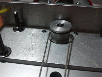
At first I had a stepper motor I wanted to use but it draw way to much current for both the shield and the battery so I switched to the dc geared.It does the job great and draws way less current. It's coupled with a smooth hub pulley taken from an old photocopier and uses a smooth belt/string also from a photocopier,the scanner part.Its basically a metallic string covered in plastic.
For the motor shield I found the unused pins and soldered pins for ease of use and to be able to be removed and disconnected if needed.Plus the +5v and ground for switches and staff.
Step 4: Connecting the Electronics


In theory the basic schematic is like in the picture. In reality I broke it down in two parts,two boards.The one holds all the switches with the resistors,the voltage regulators for the motor shield and arduino and a pot for setting the servo. The other part is the part that has the servo pins and the click relay.I do not have a schematic for this but its really basic: a transistor to power a relay witch closes the circuit for the clicker for the camera to take the picture. Because the camera needs 3 wires,the focus,the shutter and ground, i uses a switch with a led to turn on and off the focus wire.Plus an orange led that lits up while the relay is on just for fun.For the cable for the remote trigger I disassembled a remote trigger and made it to fit my 3pin plug. I have made 2 cables for an Olympus and a cannon camera. Because the 2 boards had to be far apart,the one stationary and the other on the moving part,I had to find a way to connect them together using a number of wires.So I used rj45 plugs and ethernet socket.The wire is from an old keyboard because I liked the spiral wire. Soldering the sockets proved to be tricky because its pins did not align with my pre-drilled board,so I had to improvise and soldered small wires on the socket and made a big hole on the board.
Step 5: Top Cover
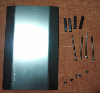


For covering it up I used an old 3.5'' hdd enclosure from cooler master.Not the best choice but I had it laying around.Used threaded rod with nuts and 4 pillars made from square carbon tube I had.Drilled holes for the switches and almost ready.The nice thing is that the side parts slide exposing the usb port of the arduino.
Step 6: Software

So, when you flip the switch in one direction on the other and if the camera has not triggered the corresponding reed switch the camera starts moving and taking photos. If you press the button while moving,the camera starts moving fast,for debugging purposes. Also If you press the button while the 3-state toggle switch is in middle(-off) there is a panorama function. The possibilities of movements combining the servo and dc motor are endless.
#include <AFMotor.h>
#include <Servo.h>
#include <SoftwareSerial.h>
SoftwareSerial mySerial(A3, A2); // RX, TX
AF_DCMotor motor(4); // create motor #4, 64KHz pwm
Servo servo;
int swDirFor=2; //forward button
int swDirBack=3; //Backward button
int swStopBeg=10; //stop1 button
int swStopEnd=A1; //stop2 button
int swPhoto=11; //sw relay for photo
int servoPin=9; //servopin
int steps=100; //step duration 1200 fotos
int servoPos=96; //middle position of servo
//int servoStart=20; //start position of servo
//int servoStop=155; //end position of servo
int servoPot=A0; //pin of servo pot
int noOfSteps=0; //count number of steps
int swFast=A5; //sw for fast movement
int i=0;//for loop
void setup() {
mySerial.begin(9600);
Serial.begin(9600); // set up Serial library at 9600 bps
servo.attach(servoPin); //servopin
motor.setSpeed(200); // set the speed to 200/255
pinMode(swDirFor,INPUT);
pinMode(swDirBack,INPUT);
pinMode(swStopBeg,INPUT);
pinMode(swStopEnd,INPUT);
pinMode(servoPin,OUTPUT);
pinMode(swPhoto,OUTPUT);
pinMode(servoPot,INPUT);
pinMode(swFast,INPUT);
digitalWrite(swPhoto,LOW);
servoMove(servoPos);
}
///////////////////////////////////////////////////////////////
void loop() {
if (mySerial.available()){
mySerial.write('a');
//mySerial.print("button stop end: ");
//mySerial.println(digitalRead(swStopEnd));
}
Serial.print("button state for: ");
Serial.println(digitalRead(swDirFor));
Serial.print("button state back: ");
Serial.println(digitalRead(swDirBack));
Serial.print("button stop Beg: ");
Serial.println(digitalRead(swStopBeg));
Serial.print("button stop end: ");
Serial.println(digitalRead(swStopEnd));
Serial.print("servo pot: ");
Serial.println(analogRead(servoPot));
Serial.print("Fast switch: ");
Serial.println(digitalRead(swFast));
servoPos=map(analogRead(servoPot), 0,1024,1,180);
servoMove(servoPos);
//forward movement
while ((digitalRead(swDirFor)==1)){
if (digitalRead(swStopEnd)==0){
Serial.println("BREAK stopEnd");
break;
}//if close
while (digitalRead(swFast)==1){
Serial.println("FF");
runMotor(0,1000);
}//while swFast close
noOfSteps ++;
runMotor(0,steps);
delay(750);//final delay(2k-1hour)
takeFoto();
} //while swDirFor)==1 close
//backward movement
while ((digitalRead(swDirBack)==1)){
if (digitalRead(swStopBeg)==0){
Serial.println("BREAK stopBeg");
break;
}//if close
while (digitalRead(swFast)==1){
Serial.println("FB");
runMotor(1,1000);
}//while swFast close
runMotor(1,steps);
// noOfSteps ++;
// servoMove(160);
delay(1000);//final delay
takeFoto();
} //while swDirBack)==1 close
//servo movement
if ((digitalRead(swFast)==1)){
Serial.println("mesa sto if");
servoMove(20);
delay(2000);//time to move servo to starting pos
for (i = 20 ; i <= 155 ; (i=i+27)){
//Serial.println("mesa sto for");
servoMove(i);
delay(2000);
takeFoto();
delay(100);
noOfSteps++;
}//for close
}//if close
delay(500);
Serial.print("steps: ");
Serial.println(noOfSteps);
}//loop close
// Routine for movement/////////////////////////////////////////
void runMotor(int dir,int steps){
switch (dir){
case 0:
Serial.println("Forward ");
motor.run(FORWARD); // turn it on going forward
delay(steps);
motor.run(RELEASE); // stopped
Serial.println("Stop Forward");
break;
case 1:
Serial.println("Backward");
motor.run(BACKWARD);
delay(steps);
motor.run(RELEASE);
Serial.println("Stop Backward");
break;
}//switch close
//delay (100);
}//runMotor close
//Routine foto//////////////////////////////////////////////////
void takeFoto(){
//delay (500);
Serial.print("CLICK!!! ");
digitalWrite(swPhoto,HIGH);
delay(1500);
digitalWrite(swPhoto,LOW);
}//takeFoto close
//Routine servo//////////////////////////////////////////////////
void servoMove(int pos){
servo.write(pos); // tell servo to go to position in variable 'pos'
Serial.print("servo move to: ");
Serial.println(pos);
delay(150); // waits 15ms for the servo to reach the position
}//servo close
Step 7: First Tries and Todo
These are my fist tries about 1200 photos and 1.5 hour of shutting time.
Moving sea.Not the best choice
Back yard nature
I also have a to-do list. Attaching a Metal ball head and some kind of way to attach tripods on both sides.
I hope you have enjoyed this instructable and thanks for reading..

Participated in the
The Photography Contest


