

Introduction: Deer Chaser


Protect your garden with the Deer Chaser Mk I. Guaranteed to protect your precious crops from voracious deer. All weather operation. 100% effective.
What you will need:
Arduino Mega 2560
Motor shield
LEDs
Parallax Ultrasonic sensor
Servo
Various wires
Ribbon cable
Cheap Tupperware
USB wall charger
Arduino cable (3 ft)
Step 1: Wiring

We will begin wiring the ultrasonic sensor and the LEDs.
You will be connecting the wires to these pins:
20
21
26
36
38
40
GND
GND
Step 2: Wiring (contd)


Now we will wire the servo to the motor shield.
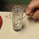
Step 3: Ribbon Cable


The great thing about ribbon cable is that you can use it as a substitute for a breadboard. Ribbon cables are far cheaper than breadboards, yet they can perform the same functions. We will be using a ribbon cable as a flexible breadboard for this project.
Step 4: Attachments - Servo


Now that we have our ribbon cable wired to our Arduino, it is time to make it useful. Gather your servo, ultrasonic, and LEDs because it's time to get them hooked up.
As the title suggests, we'll be starting with the servo.
Step 5: Attachments - LED

We'll be hooking up the LEDs now. Fairly simple operation.
If you are wondering where I got the LEDs, I got them from here -> http://www.sparkfun.com/products/11588
It is a kit that works very nicely with this project.
Step 6: Attachments - Ultrasonic

Now we will attach the most important part of this whole set up: the ultrasonic Ping sensor from Parallax.
You can get a Ping sensor from here -> http://www.parallax.com/product/28015
Step 7: Tupperware


We must protect the Arduino from the elements. This is designed to be used outside after all. Feel free to use anything you want, but I found that the best thing to use was cheap Tupperware. I was able to get 5 containers (with lids) for around $3.00. This is good because we'll be cutting the containers anyway.
We will need to make two cuts. One for the ribbon cable, and the other for the cable that will power the Arduino.
Step 8: Coding Time
Now it is time to write the code that will allow everything to work together. Fortunately for you, I saved you the trouble of doing it yourself and went ahead and prepared it for you.
Before you begin coding, make sure to choose the correct board from the compiler. We are using an Arduino Mega 2560. This code will only work with said board, nothing else. It will not work with an Uno or any of the many other Arduino boards.
To change the board in the Arduino compiler go to Tools -> Board -> Arduino Mega 2560 or Mega ADK.
Feel free to modify the code as you see fit.
/* Deer Chaser
This sketch reads a PING))) ultrasonic rangefinder and returns the
distance to the closest object in range. It then lights up a series of LEDs when the max
distance is changed.
Additionally, it starts a servo moving
To do this, it sends a pulse
to the sensor to initiate a reading, then listens for a pulse
to return. The length of the returning pulse is proportional to
the distance of the object from the sensor.
The circuit:
* +V connection of the PING))) attached to +5V
* GND connection of the PING))) attached to ground
* SIG connection of the PING))) attached to digital pin 7
created: July 28, 2013
by: Brian J. Mays
modified by:
*/
#include <Servo.h>
Servo myservo; // create servo object to control the servo
const int pingPin = 26;// pin number of the sensor's output
//adds in the lights
int RedLED = 36; // LED connected to digital pin 9 (pwm pin)
int GrnLED = 38; // LED connected to digital pin 10 (pwm pin)
int BluLED = 40; // LED connected to digital pin 11 (pwm pin)
int LED[3]={RedLED, GrnLED,BluLED}; //an array to make it easier to cycle though the LED colors
int deer_counter = 0; // Set the deer counter to zero
void setup() {
// initialize serial communication:
Serial.begin(9600);
//Set pins as output pins (lights)
pinMode(RedLED, OUTPUT);
pinMode(GrnLED, OUTPUT);
pinMode(BluLED, OUTPUT);
}
void loop()
{
// establish variables for duration of the ping,
// and the distance result in inches and centimeters:
long duration, inches, maxInches;
// The PING))) is triggered by a HIGH pulse of 2 or more microseconds.
// Give a short LOW pulse beforehand to ensure a clean HIGH pulse:
pinMode(pingPin, OUTPUT);
digitalWrite(pingPin, LOW);
delayMicroseconds(2);
digitalWrite(pingPin, HIGH);
delayMicroseconds(5);
digitalWrite(pingPin, LOW);
// The same pin is used to read the signal from the PING))): a HIGH
// pulse whose duration is the time (in microseconds) from the sending
// of the ping to the reception of its echo off of an object.
pinMode(pingPin, INPUT);
duration = pulseIn(pingPin, HIGH);
// convert the time into a distance
inches = microsecondsToInches(duration);
// change for the distance to protect
maxInches = 72;
//Serial.print(inches);
//Serial.print("in, ");
//Serial.println();
if (inches < maxInches)
{
deer_counter = deer_counter + 1;
Serial.print(" Deer Counter ");
Serial.print(deer_counter);
// turn on servo
myservo.attach(9); // attaches the servo on pin 9 to the servo object
delay(15); // waits 15ms for the servo to reach the position
//Serial.print("Detach the Servo");
// Flash the lights
for(int fade=255; fade>=0; fade-=5){
analogWrite(RedLED, fade);
analogWrite(GrnLED, fade);
analogWrite(BluLED, fade);
delay(50);
}
}
// Detach servo to turn off after IF statement
myservo.detach();
delay(100);
}
long microsecondsToInches(long microseconds)
{
// According to Parallax's datasheet for the PING))), there are
// 73.746 microseconds per inch (i.e. sound travels at 1130 feet per
// second). This gives the distance travelled by the ping, outbound
// and return, so we divide by 2 to get the distance of the obstacle.
// See: http://www.parallax.com/dl/docs/prod/acc/28015-PING-v1.3.pdf
return microseconds / 74 / 2;
}
long microsecondsToCentimeters(long microseconds)
{
// The speed of sound is 340 m/s or 29 microseconds per centimeter.
// The ping travels out and back, so to find the distance of the
// object we take half of the distance travelled.
return microseconds / 29 / 2;
}
Step 9: Check Work

All of the major components have been installed, the device has been assembled, and the code has been uploaded. Before we go any further, it is a good idea to make sure we have wired everything correctly. If you modified the code, make sure it works. If it doesn't, then I suggest using the given code for the sake of time. There will always be another chance to change it at a later date. But your plants cannot wait any longer.
Step 10: Enclosure


I will leave this final step up to you. There are many different ways to create an enclosure for this project. And everyone's garden situation is different. For mine, I used a simple wooden box, stuffed it with plastic bags, and lashed it to a metal pole.
Step 11: Deployment
It is time for the deployment of your Deer Chaser. Once you have completed this step, your garden will be protected from pesky deer and other, easily startled animals. Congratulations on completing the project, and good luck in your never ending fight against pests.

Participated in the
Microcontroller Contest

Participated in the
Arduino Contest


