

Introduction: Design. Test. Print. Build. an Aerodynamic RC Plane (Tutorial)


Recently I saw a few 3d printed RC planes on the internet, since printing the plane body and parts is low cost and the pieces are replaceable it is a great choice to build a RC plane, but many of those planes had 3D printed parts as the base structure of the plane instead of the whole body. So I thought what If the whole body of the plane was made of 3D printed parts, and started this project.
In this instructable I'm not just going to give you the .stl files and an assembly guide. I'll try to explain how to:
- Design an aerodynamic body using free software(Autodesk 123D, Tinkercad)
- Test it in a virtual wind tunnel for drag and performance(Flow Design(Free for students))
- Print the body so the outcome is light and stable.
If you just want to print and assemble the model you can skip to Step 8.
Specifications:
- Thrust: ~400g
- Weight: 400g without battery.
- Wing-span: 100cm
- 67cm long
- Chord: 17cm
--IMPORTANT!--
- If you are a beginner I do not recommend a 3D printed plane. This plane is built for aerodynamic stability but it can not withstand a crash. A foam based RC plane is much more stable for a beginner. There is a good instructable by blakehansen99 titled : How to Build Your First RC Plane for Under $100.
- I'm not any kind of expert on RC planes, Autodesk 123D, Tinkercad and Flow Design. I've been familiarizing myself with these for the past 2 months or so. I figured out to use them by trial and error so if you know a better way or if you have any idea for this project feel free to comment or contact me, so I can change those parts.
Step 1: Tools & Parts
Thrust:Weight Ratio
One important thing is the thrust:weight ratio. This ratio determines if the plane has the thrust to generate a lift force. I found some ratios for specific type of planes on the internet:
- (min)------------Trainer > 0.3 : 1
- (preferred)-----Trainer = 0.8 : 1
- (min)--------------Sport > 0.8 : 1
- (preferred)-------Sport = 1.3 : 1
This project weights 400 grams without a battery. You can add your battery weight over 400g and then calculate the thrust you need. ex: at 500 grams you will need a minimum thrust of 150 grams.
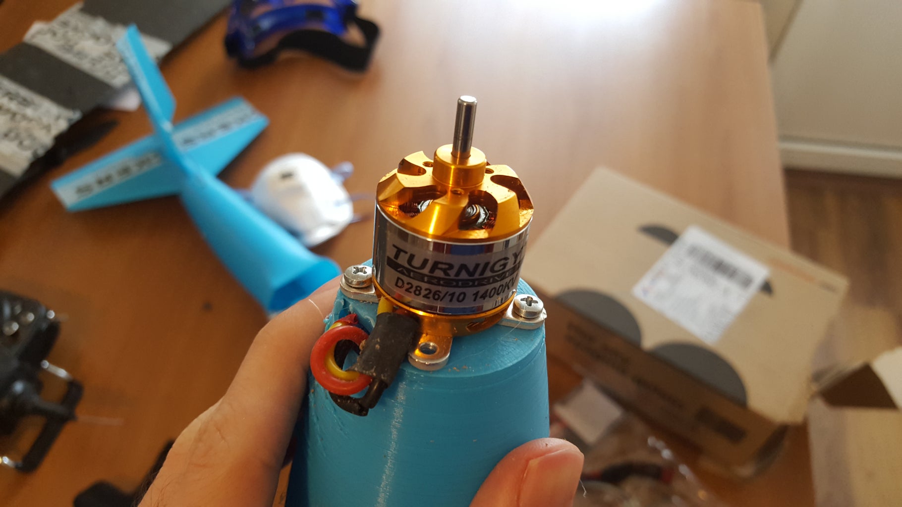
I already had an esc, 1400kv hobbyking outrunner motor and a battery lying around so I used them in this project. But these are too much for a trainer plane. So I will give you an affordable parts list,(you can choose any kind of motor-esc-battery trio as long as the thrust:weight ratio is satisfied.)
20A ESC → $10.91
Transmitter and Receiver→ $23.55
Brushless Motor(400g+ thrust)→ $10.45
3S Lipo battery → $10.79
3S Lipo charger → $4.65
9g servos(2 pieces for 3ch,3 pieces for 4ch) → $3.32
Propeller (recommended by the brushless motor)→ $2.48
Push Rods → $1.04
Foam for the wing (avaliable in home depot stores)
TOOLS:
-Hot glue gun
-Soldering Iron and solder
-Duct tape
-Rubber bands
-Super glue
Step 2: Planning


Plane Type
Since we are going to build a plane from scratch, the best thing to do first is to determine what kind of plane that you want to build. Click Here for RC Plane Types
When you decide what kind of plane to build, the next thing to do is to find dimensions of various planes of that kind on the internet.
I decided to build a Trainer model, because it requires much less power to fly, and is easy to control.
I found a really useful website for the Trainer Design click here.
Airfoil
I choose the Clark Y airfoil for my plane because it is designed for slow flights and generates much more lift force. I'm not going into details on how to choose an airfoil.
Here are some helpful links if you are interested in the details:
http://www.rcgroups.com/forums/showthread.php?t=32...
http://exp-aircraft.com/library/heintz/airfoils.ht...(math involved)
If you are going to build a Trainer my recommendation is the Clark Y airfoil. You can browse other airfoils at:
http://airfoiltools.com/ ( If you are going to choose another airfoil for your trainer look for a flat bottom, you will get more lift!)
Sketch
Based on the limits on the photo you can calculate the dimensions and sketch it on a paper. You can also use the dimesions I used.
Step 3: The Wing


There are different methods to make a wing, after watching this video by Samm Sheperd I decided to use the hot wire method for my plane, because a 3d printed wing is much more heavier than a foam wing. You can also,
create a wing out of a Foam Board → https://www.instructables.com/id/How-to-Make-a-Foam...
If you're building a trainer plane like me, you need an angle for your wings(Dihedral). For a trainer, 3-6 degrees is fine, I created an 4 degree angle airfoil in tinkercad and hotglued it between the wings. Then I duct taped a rod to top of the wings to make it stable(This is not necessary).
Attachments

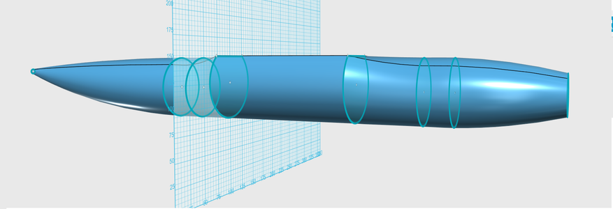
Step 4: Designing the Body


IMPORTANT!
- First read then check the images and notes.
Since I did not get into the details and basics of 123D Design here are some tutorials to get you started:
Basics(try to watch all 6):
Revolve, sweep, loft :
Basic Aerodynamics : http://adamone.rchomepage.com/index4.htm
Calculating The Factor
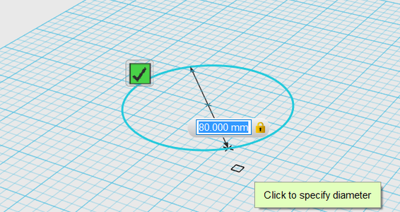
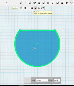
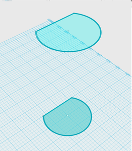
To create a thin layer of solid you need to copy paste the sketch you created and than scale it by a factor. Now I will show you how to calculate the factor:
- Check the dimension of your sketch. Let's say it is a circle and has a diameter of 80mm.
- Since We need a layer of 1mm the new circle that we scale must be smaller 1mm from each side so the diamater must be 78mm.
- The factor is calculated by New/Old(78/80) = 0,975
Here is the .123dx file if you want to edit the body in 123D Design. The .stl files for printing are avaliable at step 8.
Attachments

Step 5: The Tail of the Plane


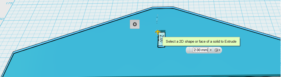

After a few test flights I realized that the tail wing is shaking in high winds(It does not effect the flight). You can use foam if you want for the tail of the plane it will be much more stable.
Attachments
Step 6: Adjustments in Tinkercad


We created the body, now we need to:
- Create a motor mount for the nose.
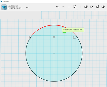
- Cut the tail for rudder and elevator.
For these adjustments I'm using Tinkercad because it is free and easy to use.
Before going into Tinkercad we need to export our objects to .stl files from 123D Design, Down Arrow>Export as 3D...>STL>Coarse(much easier to process in slic3r)
If you are new to Tinkercad I recommend the tutorials build in. They will give you the basics.
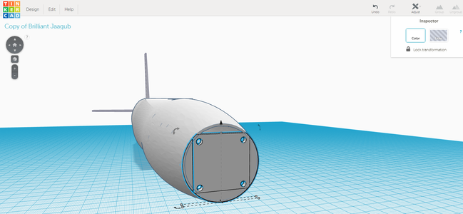
Here is the motor mount I created for a 40mm diameter nose(don't forget to leave a hole for the cables of the motor) :
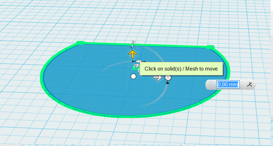
You can combine this piece with the body in Tinkercad by importing the .stl file and adjusting the piece into place.
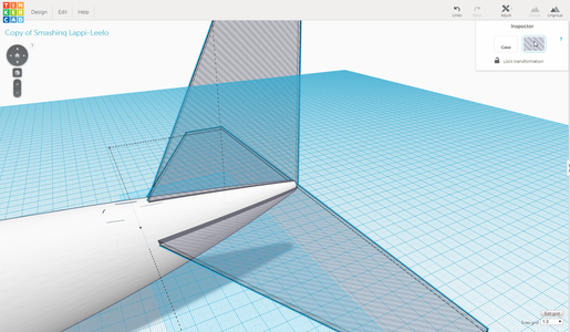
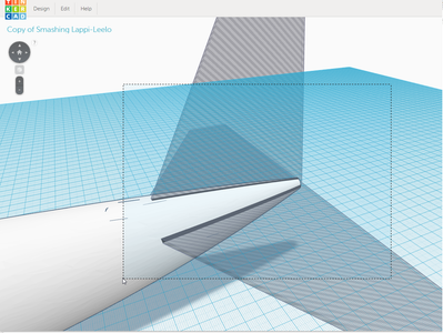
Here is the rudder and elevator pieces grouped together so you can use them to open a hole to the tail(See images for details):
Here is the final result, you can select the whole body and click ungroup to make adjustments.
We are finished with the body, now it is time to test the body for drag in Flow Design!
Step 7: The Wind Tunnel


- Download the body from Tinkercad as .stl file
- Open Flow Design
- Import the .stl file
2D
Here is a tutorial on flow lines,
What we are looking for in 2D is the flow circulation behind the object, vortex lines increase drag, so for less drag there should be less flow circulation.
3D
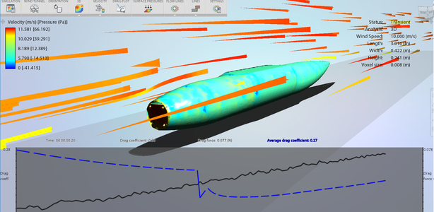
Click on 3D simulation mode. What we are looking for in 3D is the drag coefficient, the lower the drag the more aerodynamic the plane is.
To access the drag data click on Drag Plot, here you can see the average drag coefficient, give some time for the simulation to calculate the average drag(aprox. 20min)
The drag coefficient of this plane is around 0.22
Now you can compare your drag with other objects:
http://web.archive.org/web/20070715171817/http://a...
You can read more on drag:
https://www.grc.nasa.gov/www/k-12/airplane/drag1.h...
https://www.grc.nasa.gov/www/k-12/airplane/dragco....(math involved)
http://physics.info/drag/(math-physics involved)
IF,
- There is too much flow circulation behind your plane
- The drag is over 1.0
Check the surface of the plane in flow design, you should see the pressured areas as red. These areas should be changed for less drag.
In my example the front of the plane is red, but since it is the motor mount that is normal. If you have any red areas other than the motor mount, you should change your design.
Step 8: Print


I'm using a prusa i3 printer and my printer volume is x=20cm, y=20cm, z=15cm thus I have to cut the body pieces as 15cm parts.
To cut the body and export it into G-code I'm using slic3r It's Opensource and very easy to use,
Slic3r has two modes of operation, Simple and Expert. These may be chosen from the Preferences window (found under the File menu). I'm using the expert mode because it lets you customize the extrusion width(so you can change the thickness of the body).
If you are new to Slic3er you can read the user manual here: http://manual.slic3r.org/intro/overview
I uploaded the G-code files if you have a similiar printer with me,
Specs of my printer:
Nozzle Diamater: 0.4mm
Dimensions: 20x,20y,15z
Filament Diameter: 1.75mm
Also you can download the .stl files of the pieces. I included all them in the .zip file.
Here are some additional pieces that I created in Tinkercad. We will use them in the next step.
Hinge for the nose:
Landing Gear - Front:
Landing Gear - Rear:
Assembly piece:
All of the pieces are in the "parts.zip" file:
Step 9: Assembly


Here is a tutorial by Flite Test on how to connect your electronics:
I used hot glue for the servos and the landing gear, you can also use super glue if you don't plan to use them in another project.
Step 10: Test Flight


Before going out for a test flight,
You should also balance the plane, if the plane is not balanced it will be hard to control the plane. Watch this tutorial:
While going out, take some rubber bands, and some spare propellers with you. Since the motor is on the nose, it will be easy to break the propeller.
I Hope you enjoyed this Instructable as much as I did :D.
Feel free to ask any questions in the comments!

Second Prize in the
Make It Fly Contest 2016

Participated in the
3D Printing Contest 2016


