

Introduction: Design Criteria for Stirling Cycle Engine


This Instructable will describe a model Stirling cycle engine I built. More importantly, it will list design criteria, materials of construction, and tips so that you can build one of your own design.
This type engine is called a low temperature difference (LTD) Stirling engine, and there are several ways to build one, some of which are described in other Instructables on this site.
Step 1: What Is a Stirling Cycle Engine?

The Stirling cycle engine was invented by Robert Stirling in 1816, so it has been around for a while. It is a heat engine, and is based upon a cycle of heating, then cooling, of a gas (usually air) contained within the engine.Since a Stirling engine is air tight, during the heating phase the air pressure inside increases, and during the cooling phase the pressure decreases. A displacer connected to the crankshaft moves the internal air from hot side to cold side of a cylinder. The change in pressure drives a power piston, which is also connected to the crankshaft. Since there are two stages, hot and cold, it is a two cycle engine
This diagram shows the concept of a traditional LTD Stirling cycle engine.The components of the engine described in this Instructableare arranged differently, but the concept is the same.
Step 2: Components

Here are the components of the engine I built, which are similar to those shown in the previous diagram. I used copper for many of the components due to its excellent thermal conductivity. I used aluminum also; its thermal conductivity is good but not as good as copper. Both materials are very easy to work using common shop tools.
The steps that follow will describe design details of the flywheel and crankshaft, displacer cylinder and displacer piston, and the power piston.
Step 3: Flywheel and Crankshaft


I built the flywheel from a sheet of aluminum; cutting it roughly on a band saw then finishing it on a belt sander. The “hub” is made from two strips of brass bar stock, attached with machine screws and nuts. This helps align the flywheel and prevents wobble. I drilled the hubs and flywheel with a 5/32" drill and pressed in the 5/32" shaft; it was tight enough.
You can see in the photos how the crankshaft and crank pin are designed.I drilled and tapped a brass bar to thread onto the threaded 5/32" flywheel shaft. The crank pin is just a machine screw that threads onto a drilled and tapped hole in the brass bar. This way it is easy to change the crank throw distance; just drill and tap a new hole at the desired distance. Also, the phase angle can easily be changed by loosening the 5/32" nut on the crankshaft, rotating the crank throw, and re-tightening the nut.
Design details:
- Flywheel: Aluminum, 0 .100” sheet, 5” diameter
- Crank throws: Brass bar stock; 3/32” x ¼”; drilled and tapped for shaft and crank pin
- Crank pins: Machine screws and nuts, #2 screws 48 tpi
- Shaft: Brass rod, 5/32” diameter.
- Bearings: Ball bearings, 5/32” ID, 5/16” OD (from Boca Bearings)
- Hub: Brass bar stock; 3/32” x ¼”
- Crank throw distance, piston: 5/16” (so piston travel is 5/8”)
- Crank throw distance, displacer: 1.0” (so the displacer travels 2.0”)
- Phase angle between power piston and displacer piston: 90º
Tip: Brass and aluminum are easy to drill and tap. I don’t always usea proper tap, I just drill a slightly undersize hole and then use the screw as a tap. The screws are stainless steel so harder than brass or aluminum. I did use a die for threading the shaft. Use 8-32 threads for 5/32” diameter shaft.
Step 4: Displacer Cylinder and Piston


The displacer cylinder and piston can be considered a heat exchanger, because heat from a flame (in this case) is being transferred to the air inside the bottom part of the cylinder. When the displacer piston moves to the bottom of the cylinder, the air moves (is displaced) to the top part of the cylinder, which it cools. The engine makes one heating/cooling cycle each revolution of the flywheel. Since the system is air-tight, it also has an air pressure increase/decrease cycle each revolution.
The displacer cylinder is made from two sections of 2” diameter copper pipe, separated in the middle by a wood spacer. The wood serves as a thermal break between the hot section below and cooler section above. The plate at the bottom is also copper, soldered to the pipe section using 95/5 lead free plumbing solder. This solder has a melting point of 450° F (232° C), so the heat source has to be controlled. The operating temperature using two candles is 250° F (121° C). Another limitation is the temperature of the epoxy glue used to attach the copper pipe sections to the wood spacer; ordinary epoxy adhesive is OK to about 350°F (177°C). The cylinder head is aluminum, and is bolted to a mating flange, which is glued to the upper cylinder. The cylinder head is metal-to-metal contact with the upper copper cylinder, so there can be heat transfer between cylinder and head, therefore both cylinder and head can radiate the heat away and cool the air inside. I used a piece of Teflon for the bearing in the cylinder head.
The displacer piston is made from heavy paper wrapped around a 1 1/2” pipe (actual diameter 1.9”) and glued together, the ends are foam board. Shaft is 0.0625” steel wire. The displacer length is 2.0”.
Design details:
Displacer cylinder: 2” type M copper pipe, ID = 2.0”, OD = 2.125”. Gap between hot side and cold side = 3/8”.
Insulating spacer: hardwood, ID = 2.125”, drilled with 2 1/8” hole saw, then used epoxy to glue copper pipe sections to wood spacer.
Displacer piston: 1.9” diameter x 2.0” long. As a general rule, displacer piston volume should be ½ total displacer cylinder volume. Bearing in cylinder head is Teflon, with drilled 0.070” hole for 0.0625” displacer piston shaft.
Tip: The present cylinder head is 4” x 4” aluminum, 0.10” plate. For better heat transfer, it could be larger and made of copper.
Tip: Since the displacer piston volume should be 1/2 the volume of the displacer cylinder, I made the piston length 2", the total length of the cylinder being just over 4". The piston should be a "loose" fit in the cylinder; it is important that the piston not rub on the cylinder wall.
Step 5: Power Piston


The power piston and cylinder drive the engine, using pressure cycles from the displacer cylinder. They are the only purchased components in this engine. The piston is made from graphite, the cylinder is glass; the parts are manufactured to close tolerance and are practically friction free and air tight. I glued the glass cylinder into a 3/4" diameter hole bored into a block of wood; opposite the cylinder is a short length of 1/4" copper tubing.
Design details:
- Power piston and cylinder: Piston diameter 5/8”; piston stroke 5/16”. Purchased from Airpot Corporation (no, not the same company that makes coffee pots)
- Connecting rod: 3/32” brass wire soldered to brass sheet.
Step 6: Power Calculations and Performance

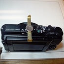
I used a shop built dynamometer to calculate power output of the engine.
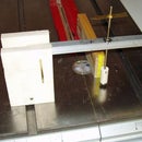
Power output of any rotating engine is based upon only two factors: torque and RPM. I used the device shown in the photo to measure torque, and could count revolutions to determine RPM. To measure torque, I made a prony brake out of balsa, then regulated the clamping force around the flywheel shaft by tightening a screw until the RPM decreased, and recorded the force on a digital scale.
P=Power, W
T=Torque, Nm
N=Engine rotational speed, RPM
Here are the equations, data and calculation:
P =T * π * N/30 or approximately T * N * 0.1047
RPM = 140
Torque arm = 200 mm = 0.2 m
Net scale reading, maximum: =1.7 g = 0.0017 kg
Force = m * g = 0.0017 * 9.8 = 0.017 N
Torque = f * d = 0.017 * 0.2 = 0.0034 Nm
Power = T * N * 0.1047 = 0.0034 * 100 * 0.1047 = 0.05 W
Not a huge power output, which is why minimum friction is so important.
Other operating data:
Maximum RPM = 175
Minimum temperature difference = 110ºF (43ºC)
Step 7: Tools

Here are specific tools:
- Set of small size wrenches (my only splurge)
- Drill press
- Table and/or band saw
- Butane torch for soldering copper
- Hole saw

Participated in the
Workshop Contest

Participated in the
Build My Lab Contest


