

Introduction: Desktop CT and 3D Scanner With Arduino


Computed tomography (CT) or computed axial tomography (CAT) is most often associated with imaging the body because it enables clinicians to see the anatomical structure inside the patient without having to do any surgery. To image inside the human body, a CT scanner requires X-rays because the radiation has to be able to penetrate through the body. If the object is semi-transparent, it is actually possible to conduct CT scanning using visible light! The technique is called optical CT, which is different than the more popular optical imaging technique known as optical coherence tomography.
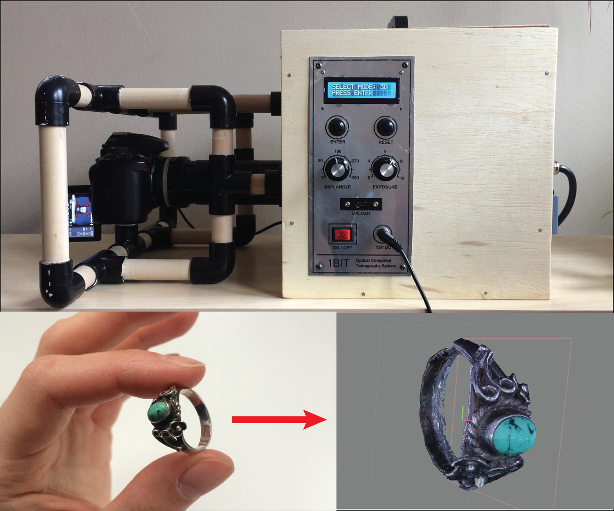
To acquire 3D scans of semi-transparent objects, I constructed an optical CT scanner using an Arduino Nano and Nikon dSLR. Halfway through the project, I realized that photogrammetry, another 3D scanning technique, requires much of the same hardware as an optical CT scanner. In this instructable, I will go over the system I constructed that is capable of CT scanning and photogrammetry. After acquiring images, I have steps on using PhotoScan or Matlab for computing 3D reconstructions.
For a full class on 3D scanning, you can check out the instructables class here.
I recently found out about Ben Krasnow built an x-ray CT machine with an Arduino. Impressive!
After posting, Michalis Orfanakis shared his homebuilt optical CT scanner, for which he won the 1st prize in Science on Stage Europe 2017! Read the comments below for full documentation on his build.
Resources on optical CT:
The history and principles of optical computed tomography for scanning 3-D radiation dosimeters by S J Doran and N Krstaji
Three-dimensional image reconstruction for CCDcamera based Optical Computed Tomography Scanner by Hannah Mary Thomas T, Student Member, IEEE, D Devakumar, Paul B Ravindran
Focusing optics of a parallel beam CCD optical tomography apparatus for 3D radiation gel dosimetry by Nikola Krstaji´c and Simon J Doran
Step 1: Computed Tomography and Photogrammetry Background


CT scanning requires a source of radiation (e.g. x-rays or light) on one side of an object and detectors on the other side. The amount of radiation that makes it to the detector depends on how absorptive the object is at a particular location. A single image acquired with this setup alone is what produces an X-ray. An X-ray is like a shadow, and has all the 3D information projected into a single 2D image. To make 3D reconstructions, a CT scanner acquires X-ray scans over many angles by either rotating the object or the source-detector array.
The images collected by a CT scanner are called sinograms, and they display absorption of X-rays through one slice of the body vs. angle. Using this data, a cross section of the object can be acquired by using a mathematical operation called the inverse Radon transform. For full details on how this operation works, check out this video.
The same principle is applied for the optical CT scanner with a camera acting as the detector and the LED array acting as the source. One of the important parts of the design is that the light rays that are collected by the lens are parallel when travelling through the object. In other words, the lens should be telecentric.
Photogrammetry requires the object to be illuminated from the front. Light is reflected off the object and is collected by the camera. Multiple views can be used to create a 3D mapping of the surface of an object in space.
While photogrammetry enables surface profiling of an object, CT scanning enables the reconstruction of the internal structure of objects. The major disadvantage for optical CT is that you can only use objects that are semi-transparent for the imaging (e.g. fruits, tissue paper, gummie bears, etc.), whereas photogrammetry can work for most objects. Furthermore, there is much more advanced software for photogrammetry so the reconstructions look incredible.
Step 2: System Overview

I used a Nikon D5000 with a 50mm focal length f/1.4 lens for imaging with the scanner. To achieve telecentric imaging, I used a 180mm achromatic doublet separated from the 50mm lens with a tube extender. The lens was stopped down to f/11 or f/16 to increase the depth of field.
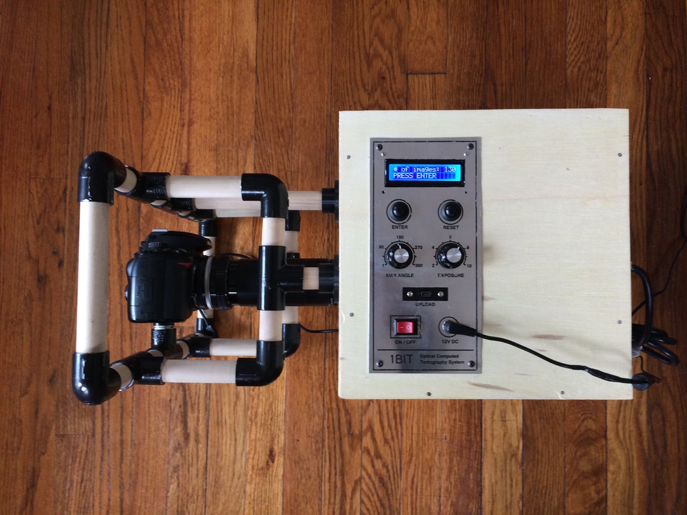
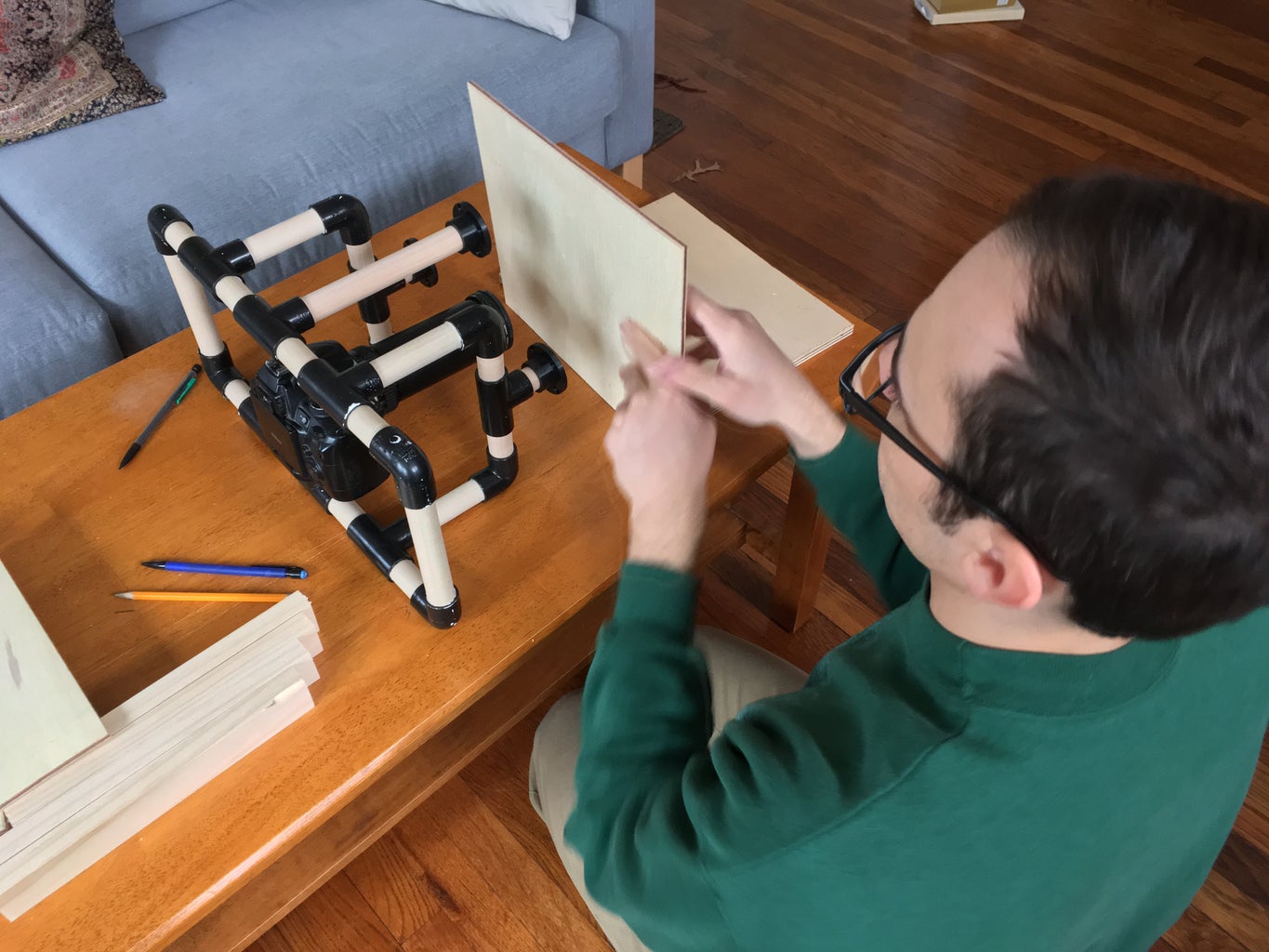
The camera was controlled using a shutter remote that connects the camera to an Arduino Nano. The camera is mounted to a PVC structure that connects to a black box that holds the object to be scanned and electronics.
For CT scanning, the object is illuminated from the back with a high-power LED array. The amount of light collected by the camera depends on how much is absorbed by the object. For 3D scanning, the object is illuminated from the front using an addressable LED array that is controlled with the Arduino. The object is rotated using a stepper motor, which is controlled using an H-bridge (L9110) and the Arduino.
To adjust the parameters of the scan, I designed the scanner with an Lcd screen, two potentiometers, and two push buttons. The potentiometers are used to control the number of photos in the scan and the exposure time, and the push buttons function as an “enter” button and a “reset” button. The Lcd screen displays options for the scan, and then the current status of the scan once acquisition begins.
After positioning the sample for a CT or 3D scan, the scanner automatically controls the camera, LEDs, and Motor to acquire all the images. The images are then used for reconstructing a 3D model of the object using Matlab or PhotoScan.
Step 3: Supply List


Electronics:
- Arduino Nano
- Stepper motor (3.5V, 1A)
- H-bridge L9110
- 16x2 Lcd screen
- 3X 10k potentiometers
- 2X pushbuttons
- 220ohm resistor
- 1kohm resistor
- 12V 3A power supply
- Buck converter
- Power jack female
- Power barrel plug
- Micro USB extension cable
- Power switch
- Potentiometer knobs
- PCB standoffs
- Prototype board
- Wire wrap wire
- Electrical tape
Camera and lighting:
- A camera, I used a Nikon D5000 dSLR
- Prime lens (focal length = 50mm)
- Tube extender
- Achromatic doublet (focal length = 180mm)
- Shutter remote
- Addressable LED strip
- Utilitech pro 1-lumen LED portable light
- Paper for diffusing light
Light box:
- 2x 26cmx26cm ¼ inch thick plywood
- 2x 30cmx26cm ¼ inch thick plywood
- 1x 30cmx25cm ½ inch thick plywood
- 2x ½ inch diameter dowel rods
- 8x L-shaped PVC joints ½ inch diameter
- 8x T-shaped PVC joints ½ inch diameter
- 1x PVC cape ½ inch diameter
- 4feet 1x2 pine
- Thin aluminum sheet
- Black poster board
- Nuts and bolts
- Spring
Tools:
- Soldering iron
- Power drill
- Wire wrap tool
- Dremel
- Jigsaw
- Wire cutters
- Scissors
- Tape
Step 4: Box Design and 3D Mounts


I designed the camera mount and box using Fusion360. The PVC pipe portion of the design was inspired by DIY steadicam jigs that are used to stabilize cameras for video. The box had to block out light from the surroundings, and provide precise alignment of the sample and the camera. To mount several of the components, I also designed several custom parts in Fusion and 3D printed them. Here is a list of the parts that I printed.
3x Dowel rod mounts to connect the camera to the black box
2x LED module mounts to connect the LED to the black box
1x Stepper motor mount
1x Object stage that connects to motor shaft
1x Object spear that connects to motor shaft
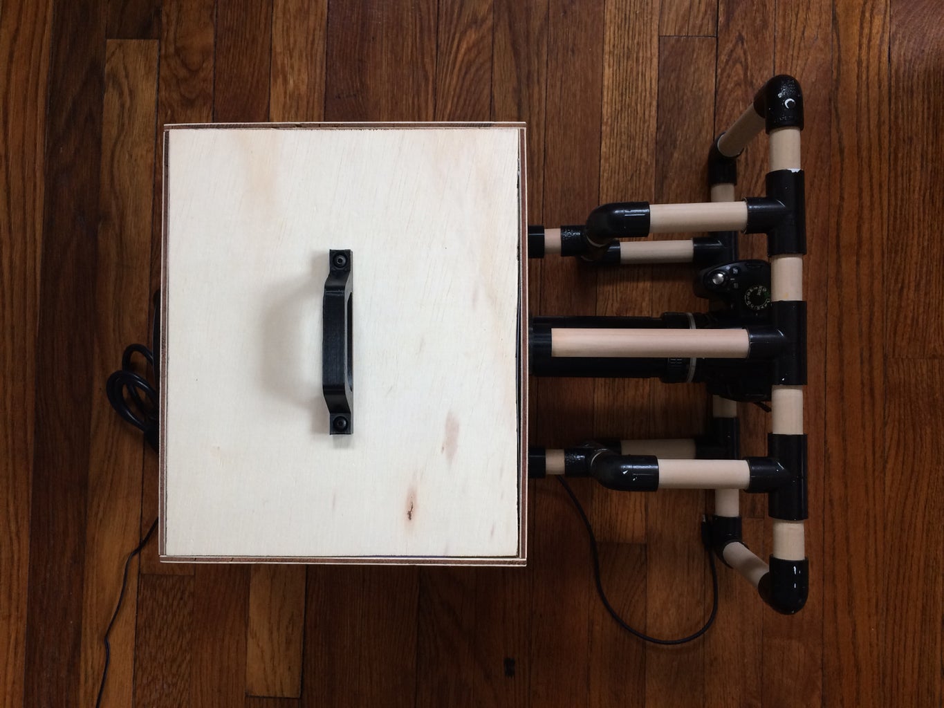
1x Handle for black box lid
2x Cable mount for fixing the LED power cable and camera remote to the light box
Once these parts are printed, you will be able to assemble the rest of the scanner. I have provided .stl files for download in this step.


Step 5: PVC Camera Mount Assembly


The PVC joints were painted black. To achieve a homogenous black, I used about five coats of black. Try your best to not get paint in the joints.
After painting, I assembled the jig for holding the camera described in this video. A hole is drilled in the bottom of one of T-joints and PVC cap. A 2 ½ inch bolt is pushed through the T-joint A spring is placed around the bolt and two nuts are used to put the spring in slight tension.
The dowels were then cut as follows using a jigsaw and wood saw:
- 1X 17cm
- 2X 14cm
- 4X 9cm
- 8X 5.5cm
- 4X 5cm
- 2X 3.2cm
After cutting the dowels, they were inserted into the PVC joints. Unfortunately, they were a much tighter fit than I expected! I had to sand down the dowels and hammer them into the joints.
Step 6: Construct Light Box


Next I built up the box using plywood and 1x2 planks. The sides were nailed into the planks, and holes were cut for the camera, LED array, and front panel. After the box was assembled, the dowel rod mounts were attached to it so that they aligned with the camera mount. The LED was also mounted using the 3D printed mounts.
To power the LED, I connected a 2.1mm x 5.5mm barrel plug into the back and ran the cable into the box. The cable was held in place using 3D printed plugs. In addition to the plug for the LED power, the remote cable also must go through the box to connect the camera trigger to the prototype board.
Finally, I created a lid for the box. The 3D printed handle was attached using two bolts.
Step 7: Camera Setup and Triggering With Arduino


Because 3D and CT scanning requires many images, automating the shutter of the camera is beneficial. For a full range of ways to do this check out this instructable by Jason Poel Smith. I decided to trigger the camera using a remote shutter and the arduino in the scanner. Cut the remote shutter cable. The wires are labeled as follows:
Yellow – focus
Red – shutter
White – ground
In order to focus the shot, the yellow wire must be connected to ground. To snap a photo, both the yellow and red wire must be connected to ground. I connected a diode and the red cable to pin 12, and then I connected another diode and the yellow cable to pin 13. The diodes protect the camera from any signals sent from the Arduino, as suggested by Jason. When a photo needs to be taken, both pins 12 and 13 are grounded. Otherwise, the pins are set to HIGH. If you don’t need to focus and snap photos separately, I think you could connect both the yellow and red cables to the same pin.
I was really stumped on using the shutter remote because I didn’t realize that there is directionality to the jack! Make sure that you have the jack inserted correctly into the camera as indicated by the arrows on the camera and jack.
Step 8: Solder Board for System


With the box assembled, I soldered the arduino, Hbridge, Buck converter, potentiometer for the lcd screen, and resistors to a prototype board. The power supply is 12V, so to power the arduino, motor, and addressable LEDs I used a Buck converter to convert the 12V to 5V. I then checked the stepper to make sure that it worked. Here is how it should be connected to the H-bridge:
- OA1 - Blue
- OB1 - Red
- OA2 - Green
- OB2 - Black
I had some issues powering the motor with the buck converter. It would randomly start moving. After troubleshooting, I connected it to the Arduino 3.3V pin with a diode so that the motor current didn't drag the 5V down.
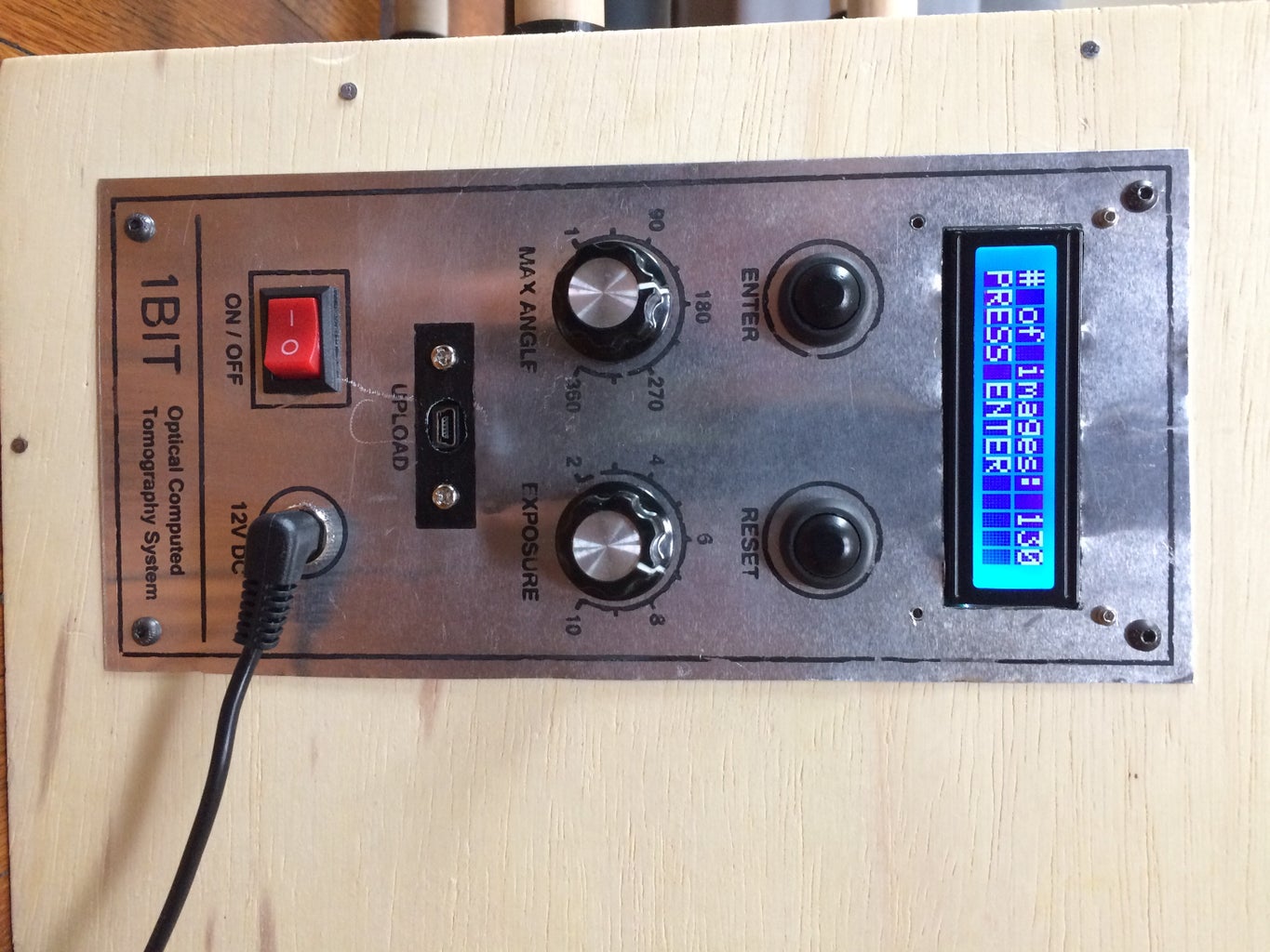
Step 9: Making the Front Panel


I wanted to try something new with the front panel, so I tried printing the panel design onto a sheet of aluminum. I followed this video by DeltaGeek. The panel design is printed backwards with a laser jet printer. Place the sheet of paper onto the aluminum panel and iron it for 10 minutes. Then soak the panel in cold water. This technique worked pretty well after trying only a few times on test aluminum. Make sure not to have the steam on for the iron!
I then drilled out holes with a drill press or dremel and attached the switches, potentiometers, power switch, usb extension cable, and power jack to the panel. Cables were soldered on before placing it into the box.
Step 10: Mounting the Panel, Motor, and Addressable LEDs


The prototype board was connected to the 3D printed mount using PCB standoffs. Then it was screwed to the bottom of the light tight box. I attached the front panel to the box and connected its components to the appropriate nodes on the prototype panel.
The motor was then screwed into the bottom panel next to the electronics and connected to the H-bridge. It is crucial that you align the motor mount with the camera lens! Otherwise, the CT constructions will be distorted.
I soldered the addressable LED strip to be placed on the wall where the lens enters the box. Initially, I attached the LEDs directly to the wood. However, after some poor scans, I decided to add black poster board to eliminate scattered light.
Step 11: Acquiring Data


The hardware for the scanner is complete! I wrote the code so the lcd screen tells the user how to run the scan. You can pick either a photogrammetry scan or a CT scan, the number of images, and exposure time of the camera. I designed two stages for the scanner: one flat table and one with a nail that can pierce soft objects for CT scanning.
The object is illuminated from the back for CT scans and from the front for surface profile scans (photogrammetry). The angle the object is rotated is equal to approximately 360degrees divided by the number of images to be acquired. For this stepper motor, there are 200 turn per revolution so the number of images acquired must be a multiple of 200. The code is written to rotate the object, pause, and snap a photo with the camera.
Once the scan is complete, the images from the SD need to be uploaded to a computer for constructing a 3D model.
Libraries required:
Attachments

Step 12: Reconstruction and Results


To see all the results from the scanner, check out my website.
CT scans:
The images for the CT scan were uploaded into Matlab, and then the images are reshaped to form sinograms. Each column in the image forms a sinogram. One of the gif above shows the sinograms for all the columns. A single sinogram creates a cross section in the image by using the inverse Radon transform.
The two other gifs play one cross section of a tomato and lemon slice at a time. You can see seeds entering and leaving the cross section demonstrating that the reconstruction successfully identified seeds at different depths in the tomato. An entire 3D object is formed by stitching the cross sections together.
I have attached the Matlab code (opticalCTprocessing.m) that processes the raw images from the camera (cropping and downsampling). I also posted several example datasets of a tomato, lemon, and apple that can be analyzed. They have already been cropped and downsampled. To process these datasets, use the Matlab file entitled: opticalCTprocessingExample.m.
Photogrammetry:
I used Photoscan on my Mac for processing the images for 3D scanning. The results were incredible! Even with the white background provided with the light box, it takes a lot of time cropping images. I am working on writing code for improving the cropping. To learn how to use Photoscan, I follow this video tutorial. The images are cropped and points are identified for the surface profile. You can see the camera positions predicted by the software, which should be in a perfect circle around the object. A sparse point cloud is created first, followed by a dense cloud, mesh, and texture.
Results:
Overall, I have been happy with the results from the scanner. PhotoScan is impressive software that does most of the work for creating incredible 3D models. I have some gaps in the photogrammetry results due to the camera being only at one elevation. For CT scanning, there were much fewer objects to scan, but I was still happy everything worked. In comparison to photogrammetry, CT scanning makes constructions of what is inside objects (even though it only works for transparent objects). Because I wrote the code, I feel I have a much better idea how the reconstruction works.
And that’s the project. Thanks for reading the instructable!

Grand Prize in the
Epilog Challenge 9


