

Introduction: Simple DIY Volume Control Knob!


Got a desktop with a sound system far from where you sit?--I do. After a bit of digging, I found that it was pretty easy to make my own soft volume control knob on the cheap.
In this tutorial I will show you how to create a USB volume control knob for your PC!
To keep things simple, Instead of Arduino, I will use an arduino compatible board called the Digispark. Not only is the Digispark small, but it is cheap! Normally I pick mine up from aliexpress.com for less than $2 USD
Lets get started!
Step 1: What You Will Need...

What you will be needing:
Micro USB cable
Micro USB DIgispark (can't be full sized version)
Rotary encoder (also cheap on aliexpress)
Not needed (but nice to have): Some sort of enclosure and knob
Arduino IDE and digispark environment.
Step 2: Time to Get Everything Set Up.

I won't teach you how to use the Arduino Development Environment, there are plenty of tutorials for that on the web already. If you are not familiar with the Digispark, setup information can be found here: https://digistump.com/wiki/digispark/tutorials/con...
Once set up, go to: https://learn.adafruit.com/trinket-usb-volume-knob... and download the Library that we will be needing for this project. Extract the .zip file and place the "Adafruit-Trinket-USB-master" folder into C:\Users\ \Documents\Arduino\libraries
Then copy and paste the sketch found on the same webpage into the Arduino IDE and upload it to your digispark.
Note:
The reason that we can do this so easily is because Adafruit has a product called the Trinket that uses the ATtiny85 chip (they have developed this simple-to-use library to work with their trinket) but the DigiSpark also uses the ATtiny85 chip!--So we can very easily use the cheap digispark to run the code and save some money!
Anyway, download the library and go to step 3!
Step 3: The Wiring

Next we can start on the hardware. I shall now demonstrate my artistic skill by drawing a simple schematic for you...
Anyway, as you can see it is very simple and that is all there is to it!
Step 4: The Build!


This is optional and depends on how you want the finished product to look (unless, of course, you just want it to sit on protoboard when you're done)
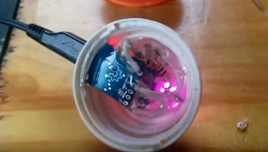
What I did was cut a small hole into a pill bottle and stick the rotary encoder though it, then I hot-glued the digispark inside the lid (remember to cut a small hole in the side of the lid for the micro USB port to connect to your computer)
Lastly I glued a piece of rubber mat to the bottom--that completes the base!
For the lid, I took the knob from an old broken stereo receiver and plopped that on top!
Note:
I also filled it with wax and iron pellets to give it a heavy quality feel, but you can watch the video to learn more about that in step 5.
Step 5: Finished!

That is it!
If you liked it, Follow meh on instagram where I post project updates: https://www.instagram.com/engineeringns/
This video may or may not be useful to you, but check it out!
If you have any problems getting it to work, contact me here on Instructables or leave a comment on the youtube video!
Also, if you find that the rotation is reversed, try changing the following lines at the top of the sketch from:
#define PIN_ENCODER_A 0
#define PIN_ENCODER_B 2
into:
#define PIN_ENCODER_A 2
#define PIN_ENCODER_B 0


