

Introduction: Digital Arduino Voltmeter With Temperature


One of my projects required the testing of aquastats, and we needed to monitor voltage (12-14vac) as well as temperature. I originally started with a TMP36 analog temperature sensor, but was unhappy with the output. It varied a few degrees every few seconds with no obvious change in the environment. I changed it out for a DS18B20 didgital sensor. I offer both versions here for your enjoyment.
For more info on this and other related projects see:
http://arduinotronics.blogspot.com/2011/03/monitoring-voltage-of-dc-battery-supply.html
http://arduinotronics.blogspot.com/2012/04/voltage-monitor.html
http://arduinotronics.blogspot.com/2013/06/ac-voltmeter-and-temperature-monitor.html
http://arduinotronics.blogspot.com/2013/06/volt-meter-temperature-monitor-part-2.html
Step 1: The Case

I dug out an appropriate case from the dumpster, milled out a rectangular hole for the lcd, and drilled holes to mount the LCD and the Arduino. I used brass standoffs and fiber washers to prevent shorts. Then I gave the whole case a quick spray of flat black to cover the scratched and scraped gray that originally covered the case.
Step 2: Voltage Divider
The first part of the code and electronics I built was the voltage divider. I like to build my projects a section at a time, and get each section working, before progressing to the next. I built the voltage divider and tested it with the serial monitor before going on to the next section.
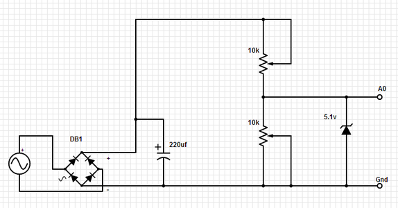
To measure voltage, you take two resistors and connect them in series. Apply your input voltage to the ends, and take a reading from the center connection of the two resistors. One end of the resistors will be connected to ground on the Arduino. We have an AC voltage we want to monitor, but will rectify it to DC first.
To learn more about voltage dividers, see http://arduinotronics.blogspot.com/2012/04/voltage-monitor.html
My first attempt at this was disappointing. When measuring a DC battery, my readings were rock solid. When reading the dc output of a bridge rectifier, they swung from full voltage to zero, and back again on a regular cycle. This was fixed by applying a capacitor across the output of the bridge rectifier, as per the schematic. If you will be monitoring a DC voltage, you can eliminate the capacitor and the bridge rectifier. The other part of the circuit is the 5.1v Zener diode from the Arduino input to Gnd. This is to prevent you from doing something foolish with the voltage divider, like presenting higher than 5v to the Arduino inputs. If the input goes higher than 5v, the Zener will conduct the excess to ground.
I calculated I needed a 3k and a 1k resistor for the voltage divider, but some adjustment might be necessary, so I used two 10k pots to give me the ability to fine tune the output.
Before connecting the output of the voltage divider to the Arduino, I plugged my DMM into the output of the voltage divider, connected the AC source, and adjusted the two pots till I got exactly 5v. Again, the 5.1v Zener prevents you from doing something foolish with the pots.
I then connected my DMM to the AC source, took the AC reading, and put it into my map command in the code as the value for 1023 on the ADC. After all the wiring was finished and the code uploaded to the Arduino, I connected the input of my AC transformer to a variac so I could run the transformer primary from 0-125vac. With my DMM on the secondary of my 29vac transformer, the Arduino LCD display mirrored the DMM almost perfectly throughout the complete range.
Arduino code as follows:
int voltPin = 0; // voltage divider (middle terminal) connected to analog pin 0
// outside leads to 0-29vac
void setup()
{
Serial.begin(9600); // setup serial
}
void loop()
{
val = analogRead(voltPin); // read the input pin
Serial.println(val); // debug value
volt = map(val, 0, 1023, 0, 29); // map 29v range
Serial.println(volt); // voltage
delay(50);
}
Step 3: Temperature - TMP36

The first version of this unit used a TMP36 analog temperature sensor. With flat side facing you, pins pointing down, this three legged transistor looking device has connections for (starting from left) +5v (pin1), data out (pin2) and Gnd (pin3).
int tempPin = 2; // TMP36 data pin
void setup()
{
Serial.begin(9600); // setup serial
}
void loop()
{
int reading = analogRead(tempPin); // read the input pin
float voltage = reading * 5.0;
voltage /= 1024.0;
Serial.print(voltage);
Serial.println(" volts");
float temperatureC = (voltage - 0.5) * 100;
Serial.print(temperatureC);
Serial.println(" degrees C");
float temperatureF = (temperatureC * 9.0 / 5.0) + 32.0;
Serial.print(temperatureF);
Serial.println(" degrees F");
delay(500);
}
Step 4: Using DS18B20 Sensors

To use the DS18B20, you need two library files (updated for Arduino 1.0), and you need to find the address of your sensor. Library files and sketches to find your address can be found at
http://www.hacktronics.com/Tutorials/arduino-1-wire-tutorial.html
http://www.hacktronics.com/Tutorials/arduino-1-wire-address-finder.html
Step 5: Reading Temperature - DS18B20

Looking for more accuracy and stability, I switched out the TMP36,for a DS18B20. This unit looks the same, but is digital instead of analog. It has an onboard address, and is a bit more complicated to use. The pin connections are reversed, as you can see from the picture. I used the waterproof version which came with 2 foot leads. This one has white for data, black for ground, and red for +5vdc. A 4.7k ohm resistor connects between white (data) and red (+5vdc).
About $2 each at http://goo.gl/X5FRN
Originally I installed the resistor and connections on the voltage divider board. I was getting the dreaded 85C/185F output from the sensor, so I figured my connections were bad. I then moved the connections directly to the Arduino, and made two unused digital ports +5vdc and Gnd by writing a high and a low respectively. I did this to keep the leads together, instead of cutting the cable apart and separating them. That did not fix the problem, so I looked over my code with a fine tooth comb. I didn't find any errors, so I created a second sketch (no cutting and pasting), and that one worked. I don't see any differences compared to the old one, but there had to be something corrupted somewhere. I've used these sensors in dozens of projects, and never had this issue pop up before. It was not a bad sensor or connection.
// This Arduino sketch reads DS18B20 "1-Wire" digital
// temperature sensors.
// Tutorial:
// http://www.hacktronics.com/Tutorials/arduino-1-wire-tutorial.html
#include <OneWire.h>
#include <DallasTemperature.h>
// Data wire is plugged into pin 3 on the Arduino
#define ONE_WIRE_BUS 3
// Setup a oneWire instance to communicate with any OneWire devices
OneWire oneWire(ONE_WIRE_BUS);
// Pass our oneWire reference to Dallas Temperature.
DallasTemperature sensors(&oneWire);
// Assign the addresses of your 1-Wire temp sensors.
// See the tutorial on how to obtain these addresses:
// http://www.hacktronics.com/Tutorials/arduino-1-wire-address-finder.html
DeviceAddress insideThermometer = { 0x28, 0x94, 0xE2, 0xDF, 0x02, 0x00, 0x00, 0xFE }; // your address will be different
void setup(void)
{
// start serial port
Serial.begin(9600);
// Start up the library
sensors.begin();
// set the resolution to 10 bit (good enough?)
sensors.setResolution(insideThermometer, 10);
}
void printTemperature(DeviceAddress deviceAddress)
{
float tempC = sensors.getTempC(deviceAddress);
if (tempC == -127.00) {
Serial.print("Error getting temperature");
} else {
Serial.print("C: ");
Serial.print(tempC);
Serial.print(" F: ");
Serial.print(DallasTemperature::toFahrenheit(tempC));
}
}
void loop(void)
{
delay(2000);
Serial.print("Getting temperatures...\n\r");
sensors.requestTemperatures();
Serial.print("Inside temperature is: ");
printTemperature(insideThermometer);
Serial.print("\n\r\n\r");
}
Step 6: Adding the LCD

Now it's time to add the LCD, and tie all the code together. The schematic below shows the connections, and the code brings all the components together.
An error I came up with had to do with displaying the voltage on the screen. If I was showing 13 volts, then dropped the voltage to 8 volts, the digit would shift to the left one position, but still show the 3 from the 13, so it ended up displaying 83 volts. This could happen with the temperature as well if the you are reading varying temperatures above and below 100 (dropping from 100.00 to 99.00). We fix this in the final code (on the voltage section) by adding:
if (volt<10) lcd.print=(" ");
before the
lcd.print(volt);
Here is the completed code:
#include "OneWire.h"
#include "DallasTemperature.h"
#include "LiquidCrystal.h"
LiquidCrystal lcd(7, 8, 9, 10, 11, 12);
// Data wire is plugged into pin 3 on the Arduino
#define ONE_WIRE_BUS 3
// Setup a oneWire instance to communicate with any OneWire devices
OneWire oneWire(ONE_WIRE_BUS);
// Pass our oneWire reference to Dallas Temperature.
DallasTemperature sensors(&oneWire);
DeviceAddress insideThermometer = { 0x28, 0x27, 0xB0, 0xBD, 0x04, 0x00, 0x00, 0xF0 };
int tempNegPin = 2; // Gnd for DS18B20
int tempPosPin = 6; // +5vdc for DS18B20
int voltPin = 0; // voltage divider (middle terminal) connected to analog pin 0
// outside leads to 0-29vac
int val = 0; // variable to store the value read
int volt = 0; // variable to store the voltage calculated
void setup(void)
{
// Used two unused digital ports as +5v and Gnd for the DS18B20
pinMode(tempPosPin, OUTPUT); // sets the digital pin as output
pinMode(tempNegPin, OUTPUT); // sets the digital pin as output
digitalWrite(tempPosPin, HIGH); // sets digital pin to +5vdc
digitalWrite(tempNegPin, LOW); // sets digital pin to Gnd
lcd.begin(20, 4); // setup LCD
// Start up the library
sensors.begin();
// set the resolution to 10 bit (good enough?)
sensors.setResolution(insideThermometer, 10);
}
void printTemperature(DeviceAddress deviceAddress)
{
float tempC = sensors.getTempC(deviceAddress);
if (tempC == -127.00) {
lcd.setCursor(0, 2);
lcd.print("Error getting");
lcd.setCursor(0, 3);
lcd.print("temperature");
} else {
lcd.setCursor(0, 2);
lcd.print("Temp ");
lcd.print((char)223);
lcd.print("C: ");
lcd.print(tempC);
lcd.setCursor(0, 3);
lcd.print("Temp ");
lcd.print((char)223);
lcd.print("F: ");
lcd.print(DallasTemperature::toFahrenheit(tempC));
}
}
void loop(void)
{
delay(500);
val = analogRead(voltPin); // read the input pin
volt = map(val, 0, 1023, 0, 29); // map 29v range
lcd.setCursor(0, 0);
lcd.print("VAC ");
if (volt<10) lcd.print=(" "); // prevents screen artifacts when dropping from 2 digit to single digit reading
lcd.print(volt);
sensors.requestTemperatures();
printTemperature(insideThermometer);
}

Participated in the
Arduino Contest


