Introduction: Digital Combination Lock!


I've always wondered how did electronic locks work, so once i finished the basic digital electronics course I decided to build one myself. And I´ll help you to build your own!
You could connect it to anything from 1v to 400v(or maybe more that depends on the RELAY), DC or AC, so you could use it to control another circuit, or even to electrify a fence!! (please dont try that, really dangerous)… I connected a mini chrismas tree to the output (110v) cause I hadnt taken the holydays decoration off my lab, so it was around at the time i finished the proyect.
Here are some pictures of the finished System, and a video too, so you can see it working.
Step 1: How Does It Work?

- First we need a circuit to decode the 10 possible inputs (0-9) to its 4 output BCD (Binary Coded Decimal), and another output that tells us when any button is pressed.
- Then we need to build the circuit for our two 7-segments displays to work properly, with 4 inputs for a BCD number and of course 7 outs for our displays, ( I used the IC 74LS47)
- Then a circuit to save each pressed number and toggle between displays
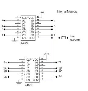
- As well as an internal memory for our password
- And, the hearth of our lock, the comparator (its 8 bits ´cause there are 4 bits per digit in the display, meaning that if you want to do a 4 digit lock you will need two of this connected together.) This will tell us if the numbers in the displays are the same as the password saved in the internal memories.
- And finally a circuit to keep the OPEN or CLOSE signal for an undetermined time, and of course an output (thats whatever you want to control with your lock)
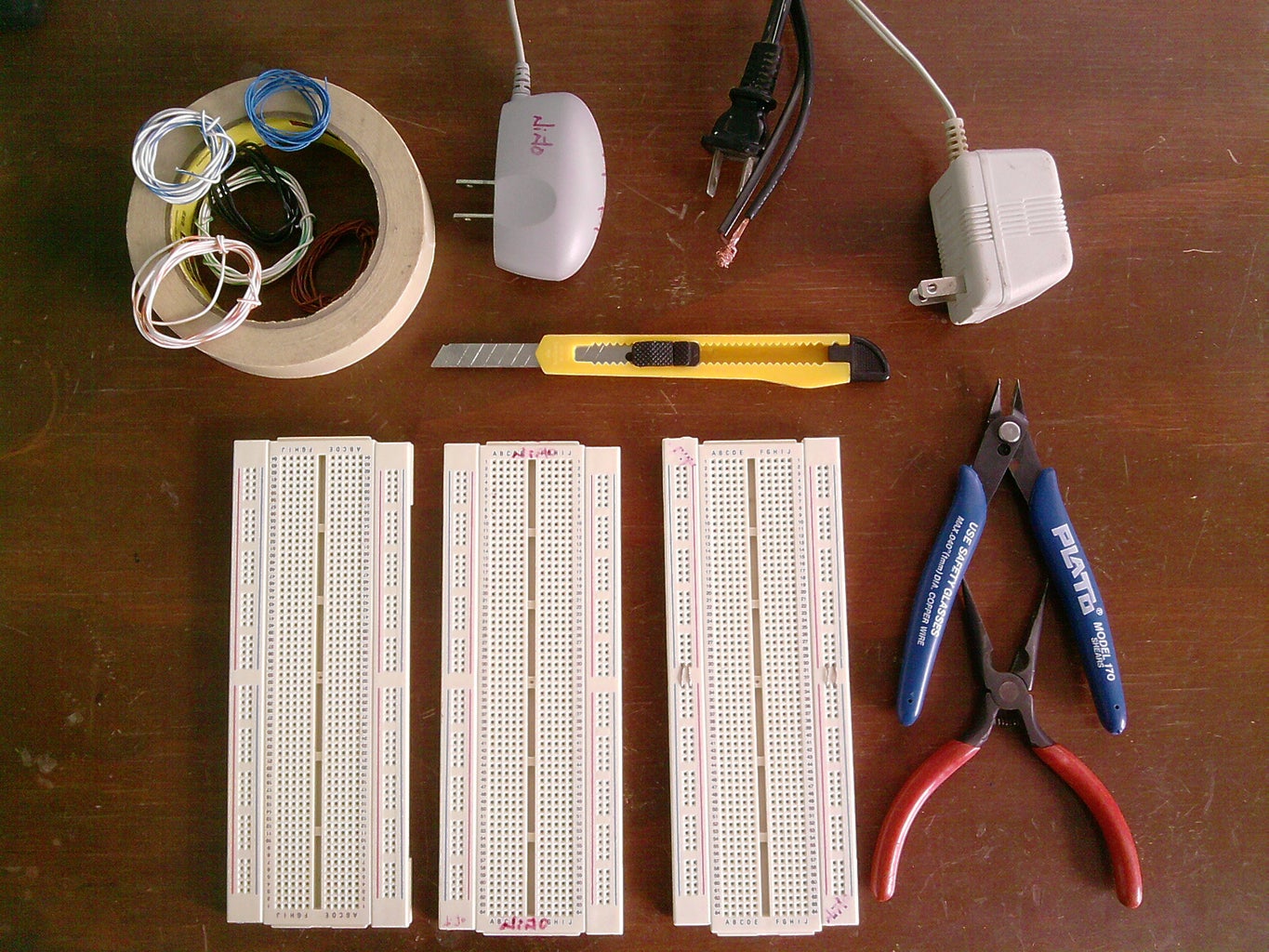
Step 2: Materials

- Lots of Diodes (about 20) to make one way connections.
- One NPN transistor ( to feed the Relay Coil with enough current)
- One Relay (to control the connected device)
- One red LED ( to indicate when the system is LOCKED)
- 14 push buttons
- Lots of resistors (doesnt really matter the resistance, its just to set the IC pins to 1 or 0[+ or -])
- Two 7-segments Displays.
- A Lot of wire!!
- Two 7432(OR GATES) to build the DEC to BCD and the comparator
- Two 7486(XOR GATES) soul of the comparator.
- Two 7447 Display driver
- Four 74175(4 D-FF) each is a memory able to hold 4 bits.
- One 7476(2 JK-FF) for the display selector and to hold the OPEN CLOSE signal.
- One 7404(NOT GATE) invert the clock pulsefor the display selector. ( you could use an NPN transistor insted, cause you need only one gate ( the ic has 6).
- 3 Protoboards (http://en.wikipedia.org/wiki/Breadboard)
- Pliers
- Exacto Knife
- 5V DC power supply(feeds circuits)
- 12V DC power supply(feeds the relay coil)
- 120V AC Power supply(feeds the device on the output)
Step 3: Dec to BCD


- Turn any of the 10 numbers from (0-9) to its BCD (binary) counterpart.(Actually, there is an IC for this purpose, but it wasnt in stock when i went to my local electronic shop., so if you get it you will save yourself a lot of time and trouble, but I think is more fun this way )
- Being able to detect whenever a button is pressed.
D C B A] X
0 0 0 0] 0
0 0 0 1] 1
0 0 1 0] 2
0 0 1 1] 3
0 1 0 0] 4
0 1 0 1] 5
0 1 1 0] 6
0 1 1 1] 7
1 0 0 0] 8
1 0 0 1] 9
E F] X
0 0] 0
0 1] 1
1 0] 1
1 1] 1
You can see we have the exact same behavior than an OR GATE, and then,Why not using just diodes, that way you will save even more Integrated Circuits, and money?...Well the answer is simple, and you should really take it in consideration, the VOLTAGE DROPPED across EACH DIODE. It´s normally about 0.65V. Why is that? Because each diode needs at least 0.6 V across its anode and cathode to make its junction get close, so it can start conducting.I
In other words, for each diode you connect and its working at the same time, you will loose 0.65 V… that wouldnt be a big problem if we were only turning leds on, but we are working with TTL IC, that means that we need at least more than 2 V. And as we are starting with 5 v.. That means that conecting 5 diodes will cause a failure in our circuit ( the integrated circuit wouldnt be able to distinguish between 0v and less than 2v…)
Step 4: Displays
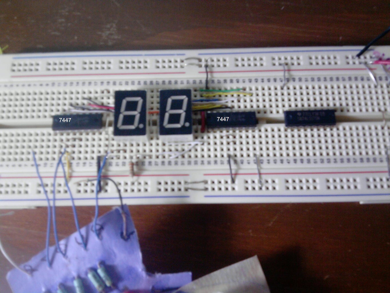

These step is one of the easiest, we just need to decode the ABCD inputs to drive the seven segment display…And luckly there´s already an integrated circuit that will save us all the logic, time and space.
If you are using a Common Anode display then you will need a 7447.
If you are using a Common Cathode display then you will need a 7448.
The wiring is the same, so either way you could use my schematic.
The inputs ABCD for each IC come from each memory´s output (we will review the memories in the next step)
Step 5: Memory


Step 6: Comparing


A a] X
0 0] 0
0 1] 1
1 0] 1
1 1] 0
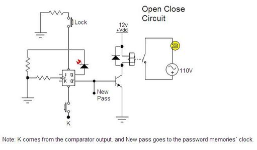
Step 7: Open/Close