

Introduction: Digital Die W/display


Digital Die w/display is a true project of engineering based on JK flip-flops by designing a counter from 1-6 with a circuit clock of variable frequency and a switch normally closed that stops the count when someone pushs its button.
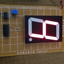
Step 1: Display/decoder Module


Display/decoder module is the monitor of this project. The parts are:
1 Dual PCB Radio Shack 276-159
1 Green Common Anode Display
1 Decoder 7447
7 Resistors of 470 Ohm
1 IC socket 16-Pin
Step 2: Power Supply Module


Power Supply module is to use a 9 Volt battery. In this module, I have included the micro-size potentiometer of 100K Ohm that isn't going to installed on circuit clock but on this module for better connection. The parts are the following:
1/2 Dual PCB Radio Shack 276-159
1 +5V Voltage Regulator 7805
2 Electrolytic capacitors of 100 microF, 50V
1 Battery Clip for 9V
1 Micro-size potentiometer of 100K Ohm
Step 3: Counter Mudule


Counter module is the heart of this project and its parts are the following:
1 Breadboard
2 7476 JK flip-flop
1 7408 AND gate
1 7432 OR Gate
1 IC 555
1 Electrolytic capacitor of 1 microF
1 Resistor of 20K Ohm
1 Slide Switch OFF/ON
1 Switch Normally Closed (Pushbutton)
Step 4: Installing Power Supply Module on Counter Module


Step 5: Connecting Display/decoder Module W/Counter Module


Step 6: Complete the Digital Die W/display


Step 7: The Design of a Counter From 1 to 6

This project was based on the design of a counter from 1 to 6. For that reason, you show how to do it.

Participated in the
Make It Glow


