

Introduction: Digital Thermometer Using Arduino

Like most of the Micro controller lovers, I also made my debut attempt at developing a simple thermometer that measures room temperature. Generally, Room Thermometers display temperature in two digits with 1 degree Celsius resolution. In such a design, two 7 segments are used, where the data-lines for both the 7 segment displays are the same and quickly switching them one after the other (theoretically, more than 16 times in a second) enables perceiving both to be ON simultaneously due to persistence of vision.
What makes my design different is that only one 7 segment display is used. First it will display the 10th place digit and then the one's place digit. The same information is conveyed in a cost-effective, compact and smarter manner. This might not seem an innovation to many, but it marks my first own innovative design.
Step 1: Components Required


My design essentially requires the following components:
1. Arduino Board
2. LM35 Temperature Sensor
3. One 7 Segment Display
4. Bread Board
5. Connecting Wires
6. Power Supply/Battery
Step 2: How Does It Work...????

For measuring temperature I am using an easily available sensor, LM35. Here, I shall remind you about the advantages of using LM35.
The LM35 series are precision integrated-circuit temperature devices with an output voltage linearly-proportional to the Centigrade temperature. The LM35 device has an advantage over linear temperature sensors calibrated in Kelvin, because the user is not required to subtract a large constant voltage from the output to obtain convenient Centigrade scaling. The LM35 device does not require any external calibration or trimming to provide typical accuracies of ±¼°C at room temperature and ±¾°C over a full −55°C to 150°C temperature range. Lower cost is assured by trimming and calibration at the wafer level. The low-output impedance, linear output, and precise inherent calibration of the LM35 device make interfacing to readout or control circuitry especially easy. The device is used with single power supplies, or with plus and minus supplies. As the LM35 device draws only 60 µA from the supply, it has very low self-heating of less than 0.1°C in still air. The LM35 device is rated to operate over a −55°C to 150°C temperature range, while the LM35C device is rated for a −40°C to 110°C range (−10° with improved accuracy). The LM35-series devices are available packaged in hermetic TO transistor packages, while the LM35C, LM35CA, and LM35D devices are available in the plastic TO-92 transistor package. The LM35D device is available in an 8-lead surface-mount small-outline package and a plastic TO-220 package.
- Calibrated Directly in Celsius (Centigrade)
- Linear + 10-mV/°C Scale Factor
- 0.5°C Ensured Accuracy (at 25°C)
- Rated for Full −55°C to 150°C Range
- Suitable for Remote Applications
- Low-Cost Due to Wafer-Level Trimming
- Operates From 4 V to 30 V
- Less Than 60-µA Current Drain
- Low Self-Heating, 0.08°C in Still Air
- Non-Linearity Only ±¼°C Typical
- Low-Impedance Output, 0.1 Ω for 1-mA Load
The Output from LM35 can be directly connected to any Analog input pin of Arduino.In the example, I have connected it to the A2 pin. As explained above, LM35 has a sensitivity of 10mV/Celsius, hence, simply I have to multiply 100 to the output of LM35 to get the temperature in Degree Celsius.
Now, to read the Analog Input using Arduino I have used
analogRead()
But in the case of UNO, M328p is the micro-controller used and it has 6 analog channels with 10-bit ADC.
This means that it will map input voltages between 0 and 5 volts in to integer values between 0 and 1023. This yields a resolution between readings of: 5 volts / 1024 units or, .0049 volts (4.9 mV) per unit.
Then, the transfer function will be like this:
0--------->5V
0---------->1023
Mathematically,
5*y=1023*x
Input voltage at ADC is x=(5/1023)*y Volts (where y is the output from analogRead() instruction)
To convert to celsius, multiply with 100.
Displaying the temperature in 7 segment is as easy as plucking a flower, but displaying it in one 7 segment requires out-of-the-box thinking. For that, I had to split the 10th and 1st digit as shown in the below piece of code:
temp = analogRead(tempPin); //Reading output from TM35 connected to A2 of Adruino
temp = temp * 0.48828125; //Converting the reading to Degree celsius
Serial.print(temp);
a=temp/10; // getting 10th place digit
b=temp%10; // getting one's place digit
Num_Write_segment(a); //displaying 10th place digit first
delay(500); // delay of 500ms
Num_Write_segment(b); // displaying one's place digit
delay(500); //delay of 500ms
Num_Write_segment(10); //7 segment display is turned OFF for 5 secs
delay(5000);
Step 3: Setting to Work..:)


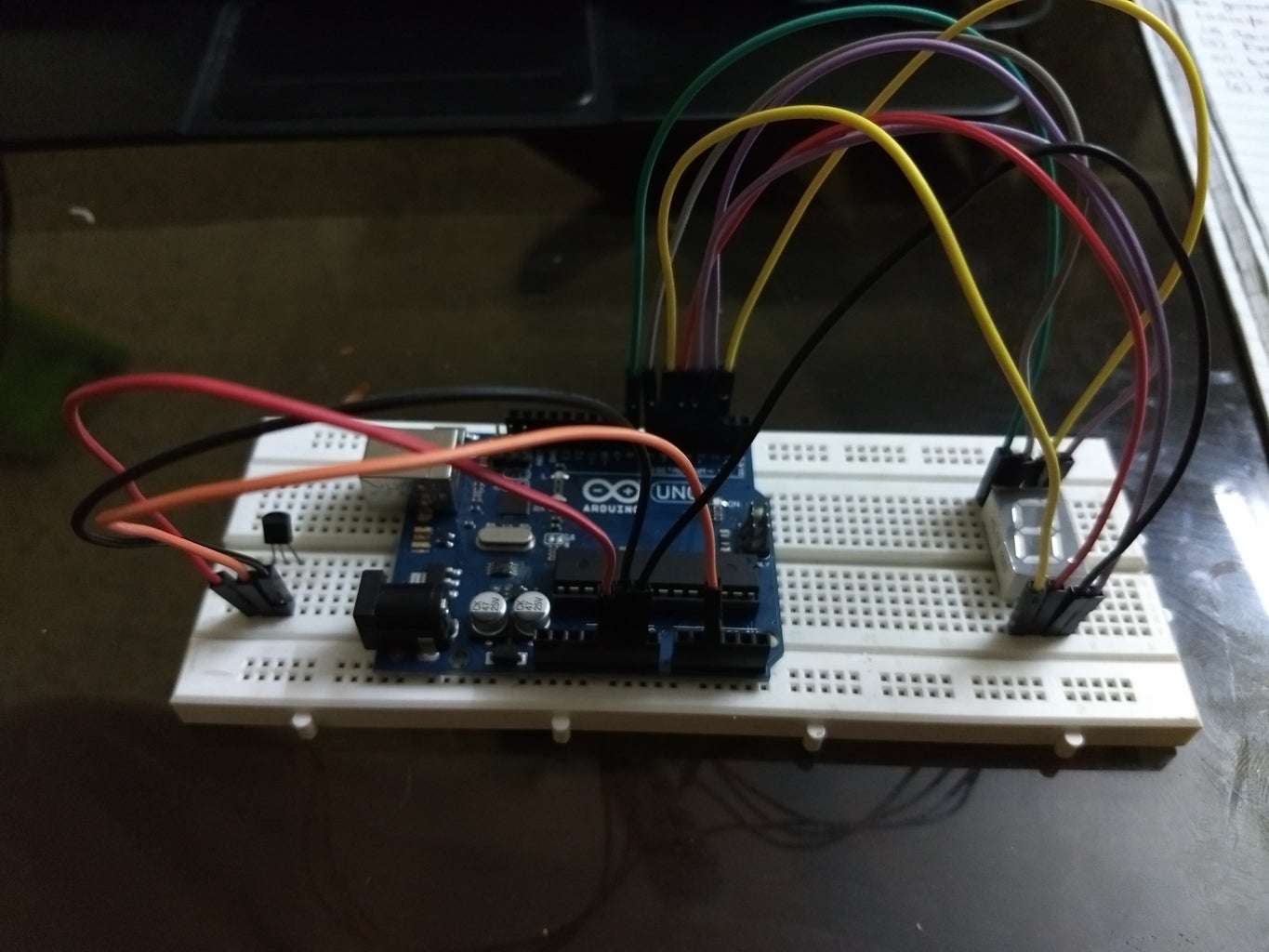
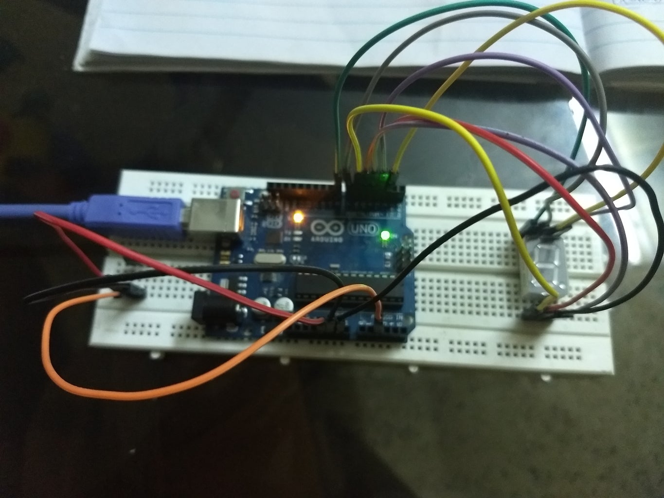
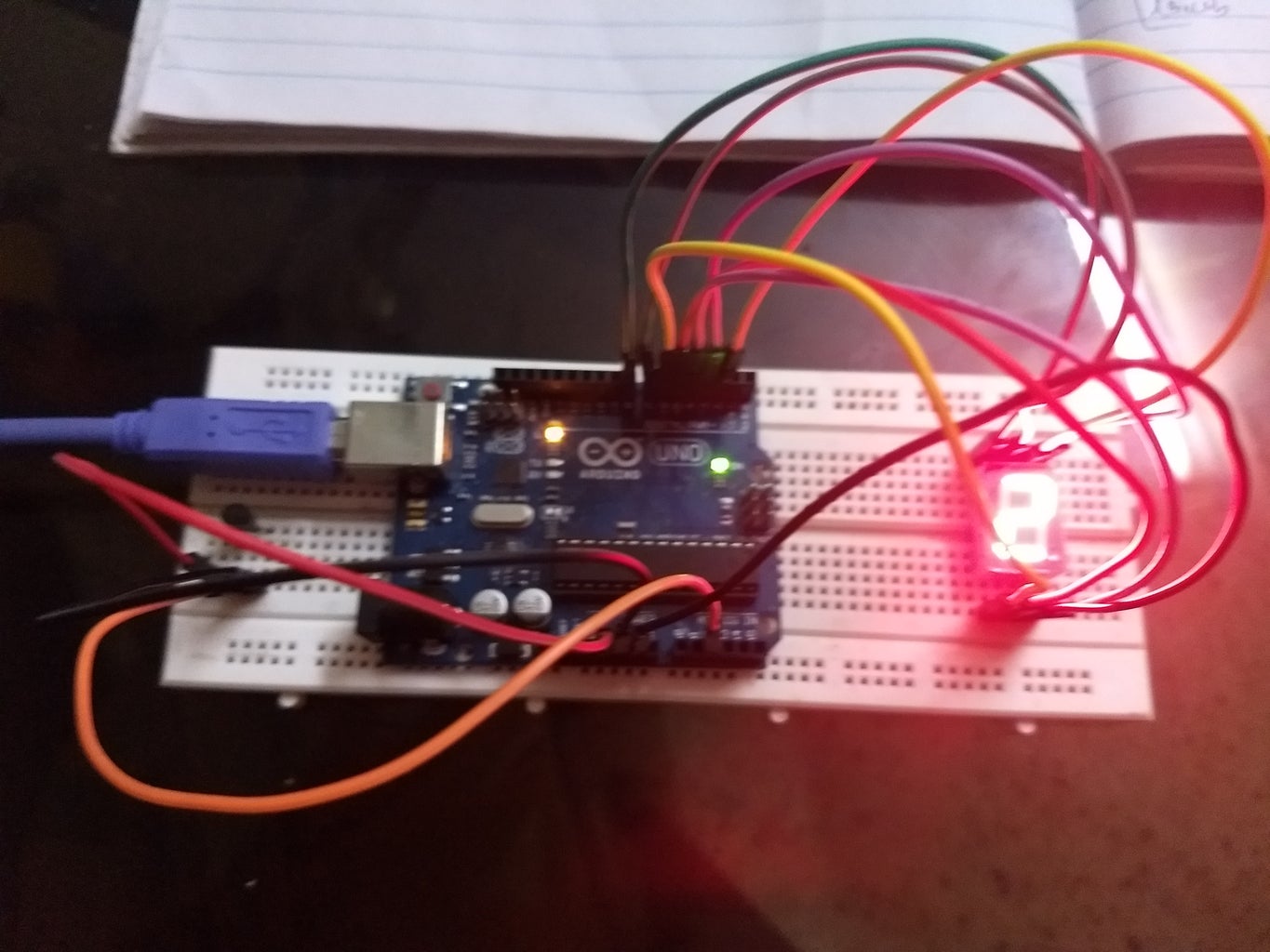
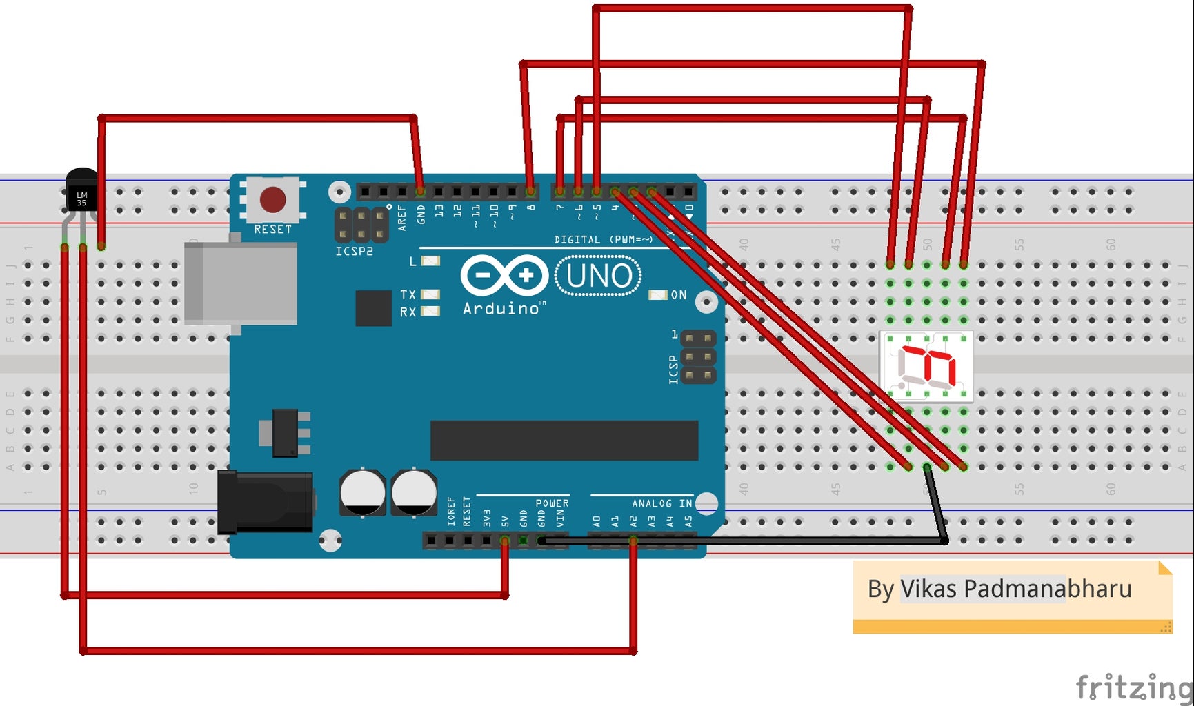
Now it's time to put the ideas and codes into work. I have attached images of the way I have arranged the components, but you may use your own setup. Make sure that the connections are as per the fritzing scheme given in the last step.
Step 4: Done With the Setup? I Have the CODE for You.. :-)
Sharing gives me that inner happiness and with digital technology, I find it very easy. Hence, I am sharing the code, which I have made, with you. You may use the code the way you want but don't forget to show the courtesy for it through proper citations.
#############################################################################################
// By Vikas Padmanabharu

int seven_num_array[11][7] = {  { 1,1,1,1,1,1,0 },    // 0
                          { 0,1,1,0,0,0,0 },    // 1
                          { 1,1,0,1,1,0,1 },    // 2
                          { 1,1,1,1,0,0,1 },    // 3
                          { 0,1,1,0,0,1,1 },    // 4
                          { 1,0,1,1,0,1,1 },    // 5
                          { 1,0,1,1,1,1,1 },    // 6
                          { 1,1,1,0,0,0,0 },    // 7
                          { 1,1,1,1,1,1,1 },    // 8
                          { 1,1,1,0,0,1,1 },    // 9
                          { 0,0,0,0,0,0,0 },     // nothing
                          };
          int a=0,b=0;
          int temp;
          int tempPin = A2;


//function header
void Num_Write_segment(int);

void setup()
{
  // set pin modes
  pinMode(A2, INPUT); // tm35 o/p is connected to this pin
  pinMode(2, OUTPUT); //
  pinMode(3, OUTPUT);
  pinMode(4, OUTPUT);
  pinMode(5, OUTPUT);
  pinMode(6, OUTPUT);
  pinMode(7, OUTPUT);
  pinMode(8, OUTPUT);


Serial.begin(9600);
}

void loop()
{
  temp = analogRead(tempPin); //Reading output from TM35 connected to A2 of Adruino

temp = temp * 0.48828125;    //Converting the reading to Degree celsius
Serial.print(temp);
  a=temp/10;                 // getting 10th place digit
   b=temp%10;                // getting one's place digit

   Num_Write_segment(a);             //displaying 10th place digit first
   delay(500);               // delay of 500ms
   Num_Write_segment(b);             // displaying one's place digit
   delay(500);               //delay of 500msNum_Write_segment(10);             //7 segment display is turned OFF for 5 secs
  delay(5000);}//
void Num_Write_segment(int number)
{
  int pin= 2;
  for (int j=0; j < 7; j++) {
   digitalWrite(pin, seven_num_array[number][j]);
   pin++;
  }
}
##################################################################################################
Step 5: Why Wait? the Code Is With You. Flash It!!!
Friends, I am showing you a video of how my thermometer works. Watch it, get inspired and try it for yourself. For any queries, feel free to contact me at vikpadma@gmail.com.
As an endnote, I would like to add the popular saying by Richard Feynman:
"What I cannot create, I do not understand"


