

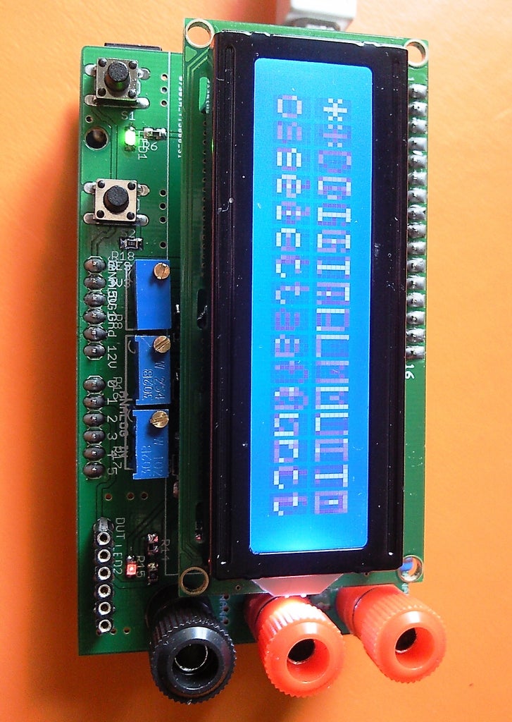
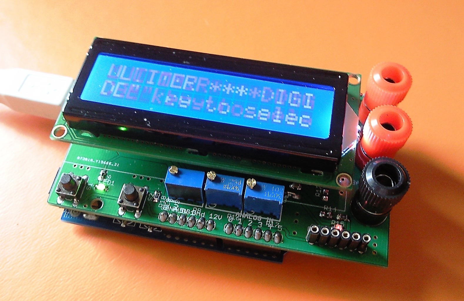
Introduction: Digital Multimeter Shield for Arduino


This instructable describes a shield, which converts "Arduino" board in a digital multimeter (DMM).
The shield can be inserted on "Arduino" UNO und Duemilanove boards. It can work in three modes:
- standalone - the measurement data can be seen at the character or graphical LCM
- connected - the measurement data can be read on the PC screen using the "Arduino" IDE "Serial monitor"
- combined - the data can be observed on both devices
The second mode does not require the presence of LCM, what makes the shield very cheap.
The "Arduino" based DMM has the following functions:
- voltmeter with 3 ranges : 0-10V; 0-30V; 0-100V
- amperemeter - it has a range 0-500mA
- ohmmeter with 2 ranhes : 0-1KOhm, 0-250KOhm
- diode, LED, connectivity checker
- LED functionality tester
- NPN BJT Beta meter
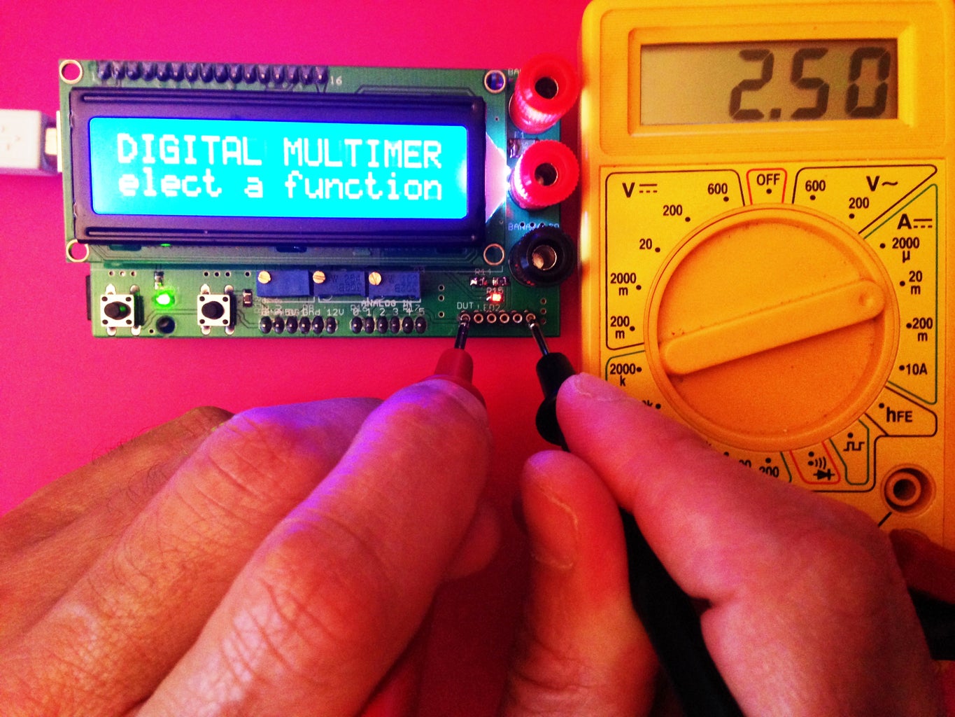
Step 1: DMM "Arduino" V/s Standard Digital Multimeter
The following movie shows how the "Arduino" based DMM works in comparison with non-professional standard DMM
Step 2: WARNINGS

I thought to add these warnings at the end, where the conclusions should be, but I have changed my mind because of the importance of this step. Before starting the copying of the design and doing some measurements the following things should be kept always in attention.
Dangerous voltages could appear at the shield nodes, connections and parts. As the shield is designed in the presented implementation, it can be used for measuring of voltages until 100 V. These voltages are dangerous for the life!!!. Even voltages close to 30 V in some cases can cause death. For this reason, all requirements concerning the work with high voltages must be met:
You should use only insulated leads. You should avoid touching of the shield parts (especially the banana socket for voltage measurements and the input resistor). You should keep your table clean - no metal parts or instruments shall be placed close to the shield because they can create short circuit between the shield parts. You should not touch any of the banana sockets and plugs during high voltage measurements. (The banana socket for the voltage measurement is not insulated in any way and touching it during operation can have deadly results!!!).
I would like to thank the user "granz" (see the comments), who reminded us about the following: When using the "Arduino" based DMM connected to the computer, you should be aware of that the ground potentials of the DMM is the same as the ground potential of you PC, and you should measure voltages and currents of device or unit, which have the same ground potential. In other case you risk to damage both - you computer and your device. If you are not sure, what the ground potential of your device is - then it is recommended to use the "Arduino" based DMM in standalone mode - supplied by battery pack or isolated DC/DC converter.
.....
Step 3: The Design Work


The main idea of the project was to create a shild for "Arduino", which can be used for voltage and current measurements. The shield had to be relatively precise ~ 1% and to be able to display the measured data on the liquid crystal display.
Starting the design, I decided to keep the circuit as simple and cheap as possible. During the design phase, I have found that I can implement some additional useful functions without big efforts and investments. Because I have used dual opamp chip and one of the embedded amplifiers was used for the ampere meter, I was looking for a way, how I could use the second one. I decided to design with its use a voltage to current converter, which further could be used for other functions : resistance measurements, diode/LED functionality checks, NPN Transistor gain measurements. This required some additional parts, but have added more functionality to the board.
Although the main two functions could be done very precise (especially with final software trimming), the additional functions have some lack of accuracy. The error in some cases can reach ~10%. The reason for that will be explained further. Keep reading :-).
There are some simple solutions, which can drastically improve also this accuracy, but they require some additional parts and are matter of possible feature project.
The schematics and the PCB board layout are presented on the pictures.
Remarks on the schematic:
- On the schematic you can see two opamp instances - they both represent only one chip, but with different packages. On the PCB both instances are placed one over other. In the reality only one chip shall be soldered. This approach makes the PCB more universal - different type of packages are supported simultaneously.
- The same design technique is used also for the transistor. It can be PMOS or PNP BJT, and it can have different packages.
- This chain is optional. The devices can be omitted. When using PMOS transistor, the LED could indicate if some device is connected for measurement : high intensity - the load is missing, low intensity - the load is connected. When using PNP BJT for the VIC (Voltage to Current Converter), it is difficult to see a change in the intensity of the LED. The advantages/ disadvantage of using PMOS or PNP will be discussed further.
The "Eagle" design files are attached to the project and are available for download and free use.
The Gerber files prepared for PCBway(fab with very cheap and high quality production) are also available for download.

Step 4: Explanation : How This Shield Works...
The schematic may look quite complicated. For that reason I will try to explain how the different functions work, separating the circuit in sub-blocks, simplifying them and showing how the calculations were done.
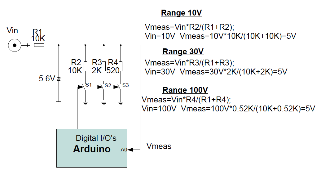
Let's start with the voltmeter. On the picture, its simplified schematic can be seen. Three voltage dividers ( for the three ranges) can be alternatively formed by use of switches controlled by the "Arduino" board. Only one switch is closed during the voltage measurement. As switches I use NMOS enhancement mode switching transistors from the type BSS123. They have typical Ron around 6-10 Ohms, which does not influence a lot the accuracy for the ranges 0-10V, 0-30V. For the range 0-100V, their Ron is taken into account, when calculating the voltage divider ratio.
The Zener diode is used to clamp the Vmeas potential ( the voltage applied to the analog input A0 of the "Arduino") at 5.6V and to protect the Atmel chip. Its clamping value is taken with the presumption, that the board will be supplied with 5V source. This Zener diode must be very carefully chosen. I took one of ten measured. It must satisfy two criteria:
- The clamping voltage must be not higher than 5.6V
- The current flowing through the diode in reverse connection, when 5V are applied on it must be close to 0. If significant current flows, this will affect the measurement accuracy and will introduce some non linearity. The diode, which I soldered was passing only 1uA.
Step 5: How the Current Is Measured...
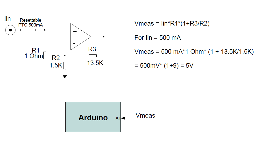
You can see how the current is measured on the presented schematic diagram.
The measured current is passed through 1 OhM resistance to the ground. Amplifier, which output is connected with the "Arduino" analog input A1 is amplifying the voltage drop over the resistor with gain 10.
To prevent damages, when higher then desired current is applied at the ampere meter, I have put a resettable PTC for 500mA.
Step 6: How the Resistance Is Measured....


A reference voltage with respect the positive supply range is created by the use of the Zener diode (2V). The generated in this way voltage reference is applied to the input of voltage to current converter realized by the opamp and the PNP BJT (PMOS) transistor, at which emitter (source) terminal, adjustable and commutable resistors are connected. The voltage over these resistors is identical with the voltage over the Zener diode. The "Arduino" board controls, which of both switches will be closed, defining in this way through which of both resistors will flow current. Thus two possible current values are possible: 10uA, 2.5mA. These currents can be adjusted very preciously. The generated so current is passed through the measured device (resistor, diode, LED, transistor) and the voltage drop appeared over the device under test (DUT) is applied to the analog pin A2 of the "Arduino" board.
For the VIC (voltage to current converter) can be used as well PMOS or PNP bipolar devices.
At the first try I was using PMOS NDT2955 device. (I had one available, and decided to use it). The opamap used was LM358.
Making some tests, I have found that some measured data is not stable. I found that oscillation appeared. The VIC was not stable.
The reason for that was: The maximal capacitive load, which the LM358 can drive is less than 50pF (without resistive isolation).
The gate capacitance of the used PMOS was 600pF, which was making the whole circuit unstable. Then, I have changed the transistor with PNP BJT (Bipolar Junction Transistor) 2n3906, and the circuit was stabilized.
In other words: the type of the opamp and transistor of the VIC must be carefully chosen. The LM358 is not the best choice - it has stability problems with high capacitive loads, it has sensible offset and the output swing is not the best. If more precision is required better to be chosen an R2R (rail to rail) input/output opamp with JFET/CMOS (low input current) inputs, with low offset.
The higher offset in my case would be useful "feature", because further, in the software tuning part, I would like to show, how this offset can be corrected by the use of the software.
Using the PMOS transistor, will allow us to use the "load/no load" function of the Ohmmeter, but could create stability problems.
Using PNP BJT has the advantage that the circuit is stable.
In both cases, independently, which type devices are used (OK..mostly for the PMOS), they create small accuracy problems.
The reason for lower accuracy is the limited output resistance of both devices. What is this meaning:
Lets take the resistor range 1000 Ohm. In this case, reference current of 2.5mA are passed through the resistor, and the generated voltage is applied to the ADC input of the Atmega chip. The resistor value, which we want to measure can vary between 0 Ohm and 1000 Ohm. The voltage Vmeas in this way also varies between 0V and 2.5V. The Vce (Vds) : Collector-emitter/ Drain-source voltage varies between 0.5V-3V. The variation of the mentioned voltage affects directly the collector-emitter / drain-source flowing current, what finally results in worse accuracy. The described phenomena can be better understood looking on the typical NPN BJT transfer characteristics presented on the picture.
This effect can be in some limits corrected by the software, but if some non linearity effects are available, the correction becomes very difficult.
Step 7: How the Beta Is Measured....

The current, which generation was explained in the previous step is passed through different devices : resistors, diodes, LED's, Schottky diodes...etc. The generated voltage drop over the corresponding device is measured. This voltage can serve as information obout the functioning of the device. For example, the Vf (the voltage drop over the device, when connected in forward direction) can vary for:
diodes - 0.4V- 0.8V
Schottky diodes - 0.1V-0.5V
LED (depend on the color) - 1.1V-3.5V...etc.
For this check, the current of 10uA is used.
If the current 2.5mA is passed though the mentioned devices, these voltages become higher. The LED's start to glow. This is way to test securely the functionality of LED diodes. (The white ones could not glow - sometimes they require over 3V).
The current with value 10uA is used also for the NPN BJT Beta (Hfe) measurement . The circuit and the corresponding calculation for this can be seen on the picture
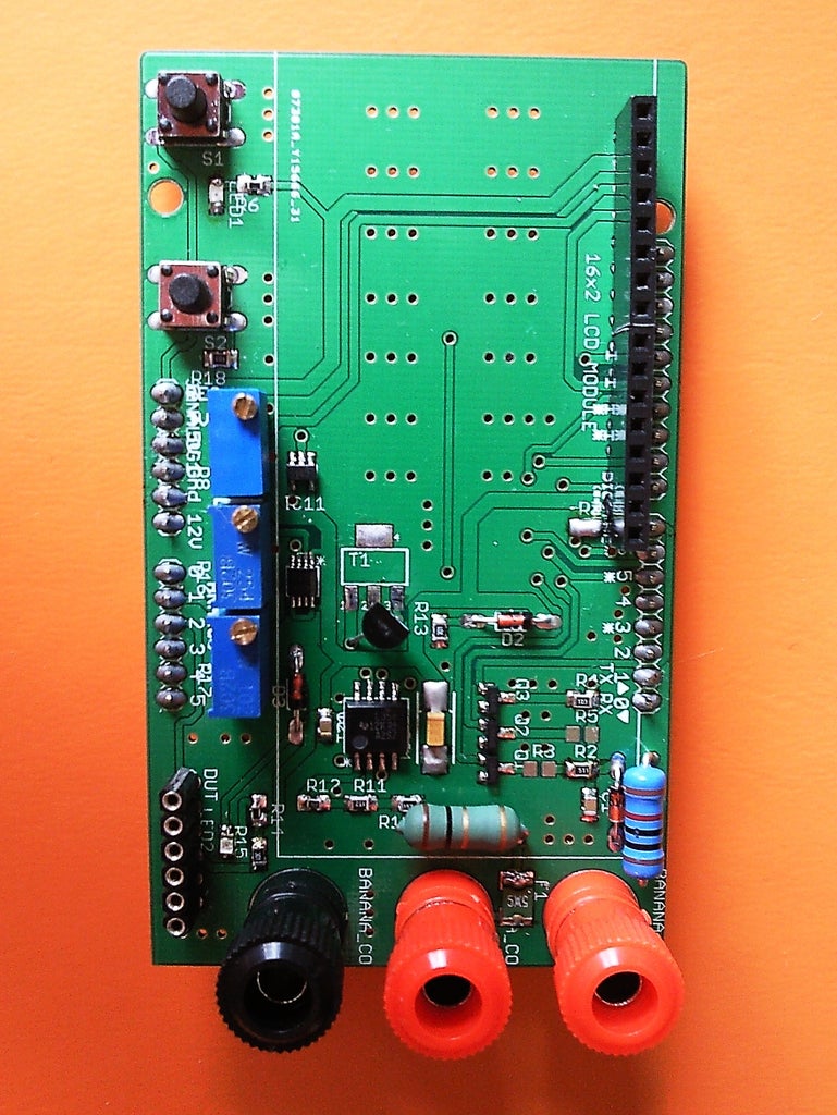
Step 8: The Parts List (BOM)

Part Value /Name Package
C1 100nF C0805
C2 100nF C0805
C21 10u 085CS_1AR
D1 Zener 5.1V DO34Z7
D2 Zener 2V DO34Z7
D3 Zener 2V DO34Z7
F1 MF-MSMF050-2 500mA- L1812
resettable PTC
IC1/U1 LM358 SO08 0r
LM358 SOIC08
IC11 74LVC1G14DBV SOT23-5
U2 SN74LVC2G66_DCT_8 DCT8
LED1 GREEN SMD LED CHIPLED_0805
LED2 RED SMD LED CHIPLED_0805
Q1 BSS123 SOT23
Q2 BSS123 SOT23
Q3 BSS123 SOT23
Q4/T1 2N3906 TO92 Or
NDT2955 SOT223
R1 10K 1W 0207/10
R2 10 R0805
R3 510 R0805
R4 10K R0805
R5 2K R0805
R6 1K1 R0805
R7 510 R0805
R8 10K (trimmer pot.) RTRIM64W
R9 1 1W 1% 0207/10
R10 1.5K R0805
R11 12K R0805
R12 1.5K R0805
R13 300 R0805
R14 300 R0805
R15 300 R0805
R16 250K (trimmer pot.) RTRIM64W
R17 1000 (trimmer pot.) RTRIM64W
R18 10K R0805
S1 microswitch B3F-10XX
S2 microswitch B3F-10XX
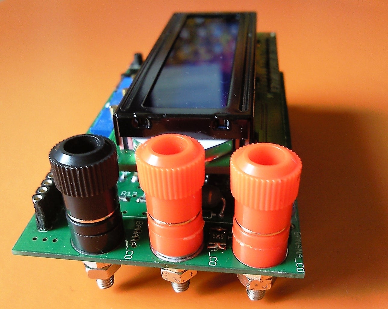
U$1 Banana connector socket 4mm
U$2 Banana connector socket 4mm
U$3 Banana connector socket 4mm
U$4 16x2 LCM (Character liquid crystal display module) . Very cheap (2.25 USD) at ebay. Not needed if you want to use only the serial monitor mode.
Header connectors - male and female
DUT IN GND e c b e 1X06
JANALOG 6x1F-H8.5-L14.5mm 1X06
JANALOG1 POWER 1X06
JHIGH 10x1F-H8.5-L14.5mm 1X10
JLOW 8x1F-H8.5-L14.5mm 1X08
Step 9: PCB's...
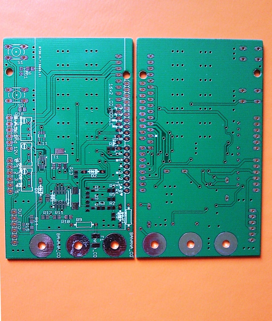
The PCB's were ordered in the fab and after two weeks they came.
Step 10: Soldering...

All the parts were soldered. I have decided to solder female header for LCM. On the LCD module, I have soldered pin headers. In this way I can simply attach and detach the display when needed or to use it for other projects :-).
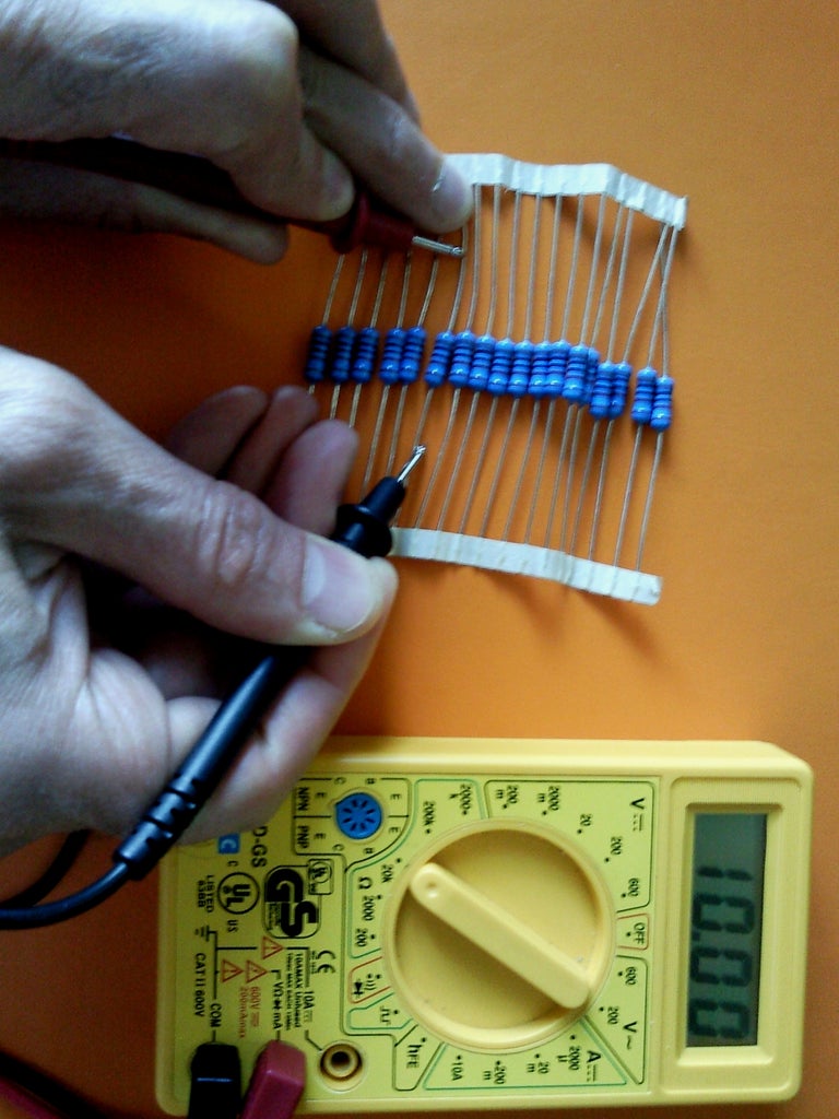
When was possible, I tried to chose the most precise parts, from those available at home.
Step 11: Some Explanation About the PCB


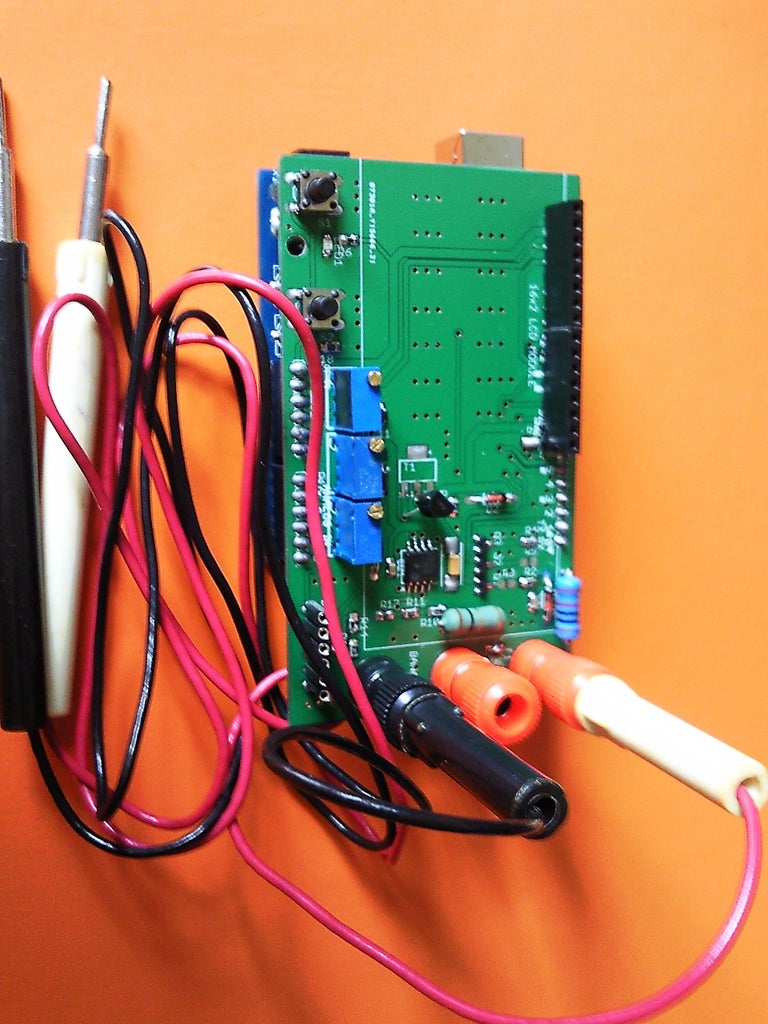
On the pictures can be seen how the tested devices (resistors, diodes, Schottky diodes, LEDS are inserted)
Step 12: Let's Start the Tests

As first step I wanted to test the LCD connection and control correctness. For that purpose I used the well known "Hello world" example available in the "LiquidCrystal" library with small modifications.
My LCM has different connections, as described in the example. The reason for that is - I wanted to have the "Arduino" digital pin #2 free, because I wanted to use the interrupt attached to this pin for other purposes.
The pin connections are the following:
LCM 1602 Arduino
D4 6
D5 5
D6 4
D7 3
E 11
RS 12
RW - connected to ground
Additionally, I have connected the display back-light LED "K" pin to the "Arduino" digital pin 10. I wanted to be able to fade the back-light and to create some effects ( "Overflow") .
The modified "Hello world" sketch is attached.
Attachments
Step 13: Functions Definition
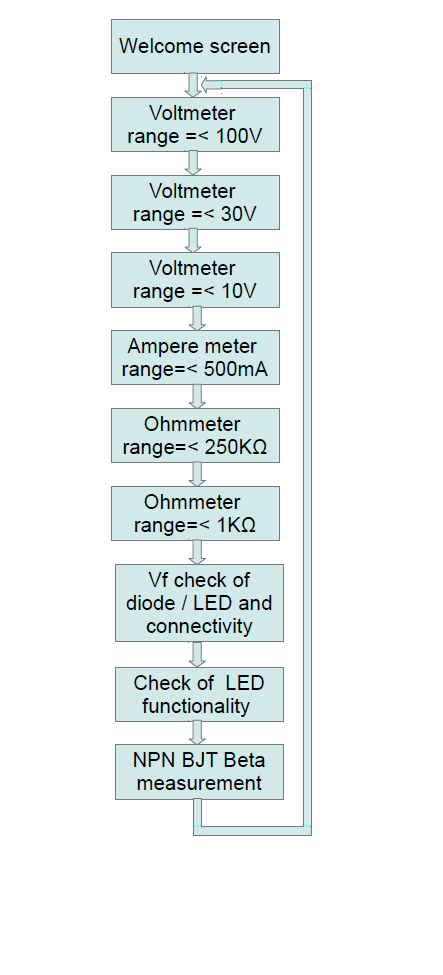
The next step was to defined the all functional modes. I have counted 9 of them. They are shown on the picture.
Now the idea was to test the functional mode selection. I wanted that all the modes roll one after the other in one direction, by pressing the switch called "MODE". There are two switches on the shield board - the first duplicates the reset button of "Arduino", the second one is the "MODE" switch. As mentioned before, this switch is connected with pin #2 of the "Arduino" board. To this pin is attached the hardware INT0. Using the interupt, I have implemented debouncing of the switch. The debouncing and the menu state machine was tested with the attached sketch.
Attachments
Step 14: The DMM Software
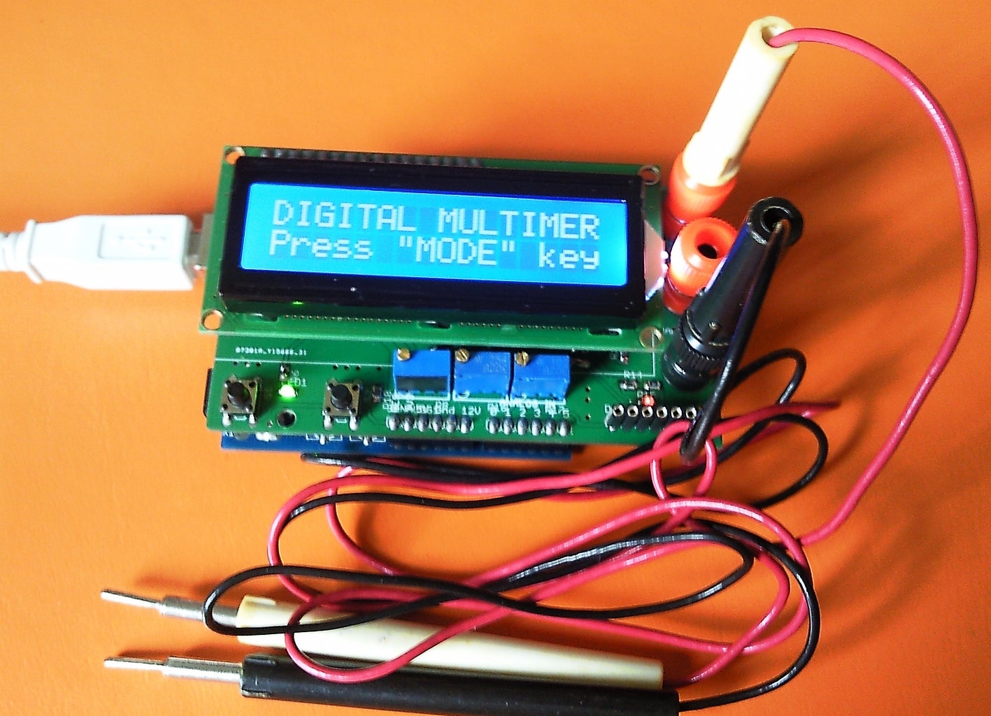


After successful finishing of the previous tests, the main working DMM software was written.
The code is attached in the *.ZIP file.
I will explain only some main functions, the other simply repeat them:
The function for voltmeter (range 0-100V) :
void V_100() {
digitalWrite(v100, HIGH);
lcd.clear();
lcd.print("V-meter V=<100V");
Serial.println("* Voltmeter mode - Range 0 - 100 V *");
lcd.setCursor(0, 1);
voltage_meas();
}
prints some messages on the screen and calls the function voltage_meas() :
void voltage_meas() {
acc_value = 0;
for (int i=0; i <= 15; i++){
curr_value = analogRead(A0);
acc_value = acc_value + curr_value;
}
curr_value = int(acc_value/16);
if (curr_value == 1023) {
meas_overflow(); }
else {
switch (MODE) {
case 1:
disp_res = ( curr_value*supply*20)/1024*coeff_v100 ;
break;
case 2:
disp_res = ( curr_value*supply*6)/1024*coeff_v30;
break;
case 3:
disp_res = ( curr_value*supply*2)/1024*coeff_v10;
break; }
lcd.print(" V = ");
lcd.print(disp_res, 2);
lcd.print(" V");
Serial.print("* V = ");
Serial.print(disp_res, 2);
Serial.println(" V");
delay(250);
}
}
, which take 16 consecutive samples and
averages them. If the result is less than 1023, it converts the ADC word to corresponding voltage value and displays it on the screen. During this calculation, some trimming factors are added. First of them is the measured preliminary supply voltage (it is used as reference for the AD conversion), the second one tries to correct the devices mismatch. It is close to 1.00, but in some cases can differ few percents. This coefficient is determined empirically during the tuning phase. Explanation will follow.
If the result after the averaging of the 16 samples is 1023 the "meas_overflow" is called.
void meas_overflow() {
lcd.setCursor(0, 1);
lcd.print(" OVERFLOW!!! ");
Serial.println("* OVERFLOW!!! *");
lcd.setCursor(0, 1);
for (int i=0; i <= 101; i++){
analogWrite(back_light, brightness);
brightness = brightness + fadeAmount;
if (brightness == 255) {
fadeAmount = -fadeAmount ;
}
delay(15);
}
}
In this procedure the back-light is faded and a warning is displayed.
On the pictures can be seen the functioning DMM in different modes and functions.
P.S. Thanks to jfrontone, we have found a possible problem in the code.
It is in the button_pressed() procedure.
if the increment MODE=MODE++; does not work (sometimes this depends on the microcontroller chip or on the IDE version), you can write either MODE=++MODE; or MODE=MODE+1; . Until now no-one has reported about such problem in the "for" control structure - for example for (int i=0; i <= 101; i++)...
Step 15: Software Tuning of the Accuracy (part 1)
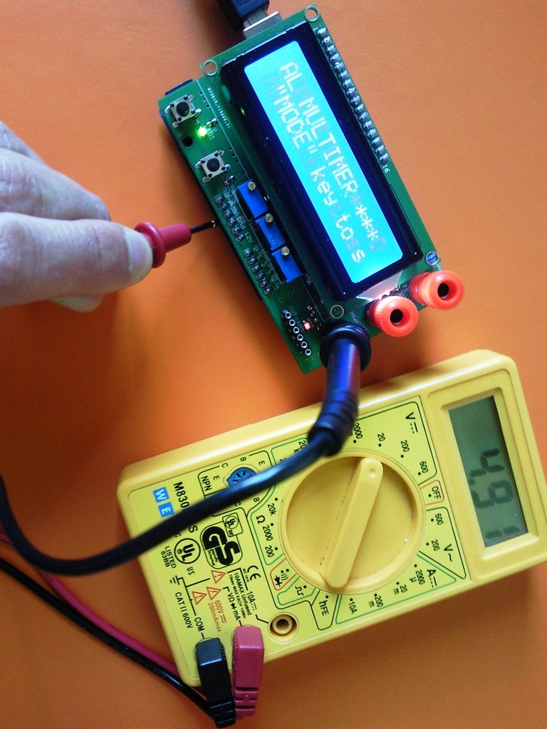
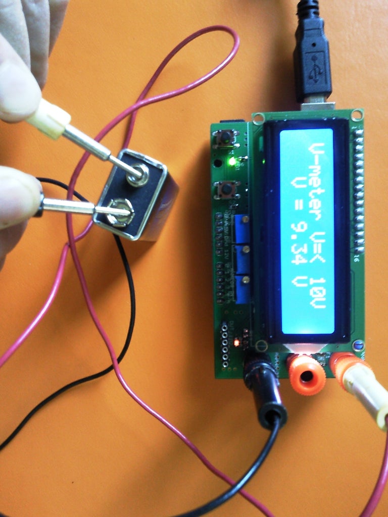

Let's as first step to trim the voltmeter.
I will show how to do this for the range 0-10V. The other ranges are trimmed in the same way.
To trim the accuracy for a given range the best approach is to chose trimming reference voltage, as close as possible to the upper limit of the range. Once trimmed for this voltage is assumed that, because of the linearity of the voltage divider and the AD conversion , the whole range is covered with the same accuracy. To trim the voltmeter for the range 0-10V I have taken new 9V battery.
As first step I have measured the power supply voltage at the "Arduino" board supply header. In my case it was 4.91V.
This voltage serves as reference for the ADC of the Atmega chip. It is included in the formula for the conversion of the taken ADC reading to voltage value:
disp_res = ( curr_value*supply*2)/1024*coeff_v10;
, where :
disp_res - is the voltage value displayed on the screen;
curr_value - is the averaged digital reading;
supply - is the measured power supply voltage ;
coeff_v10 - is the software trimming coefficient
The next step is to measure the battery voltage by the standard DMM and to write the value.
After that we measure the same battery with the "Arduino" based DMM. Based on both measurements we calculate the trimming coefficient coeff_v10 as quotient resulting of the division of the first measurement result by the second measurement result. In my case I have measured the battery with the standard DMM to be 9.51V. Measured by the "Arduino" DMM it was 9.34V.
The correction coefficient was calculated as:
coeff_v10 = 9.51/9.34 = 1.018
The resulting value is assigned to the coeff_v10 in the code.
After recompiling and loading the code it is seen that after the trimming the "Arduino" DMM shows the target value.
I would recommend that this coefficient is calculated for few voltages measured with the same range settings and the final value entered in the code is the averaged of all calculated.
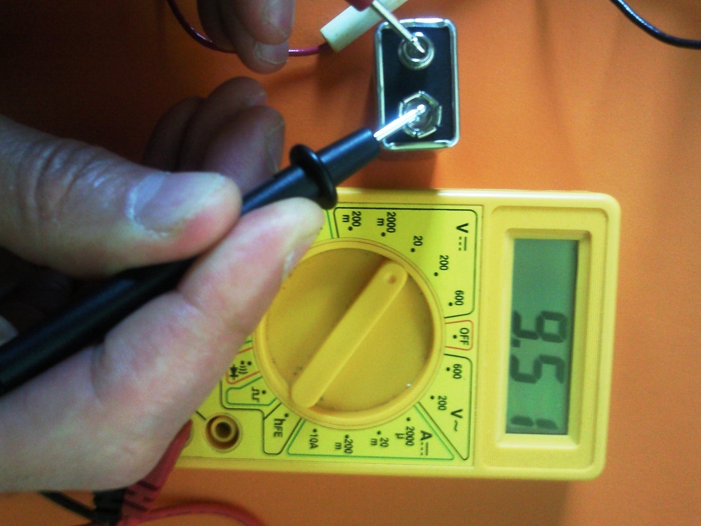
Step 16: Software Tuning of the Accuracy (part 2)


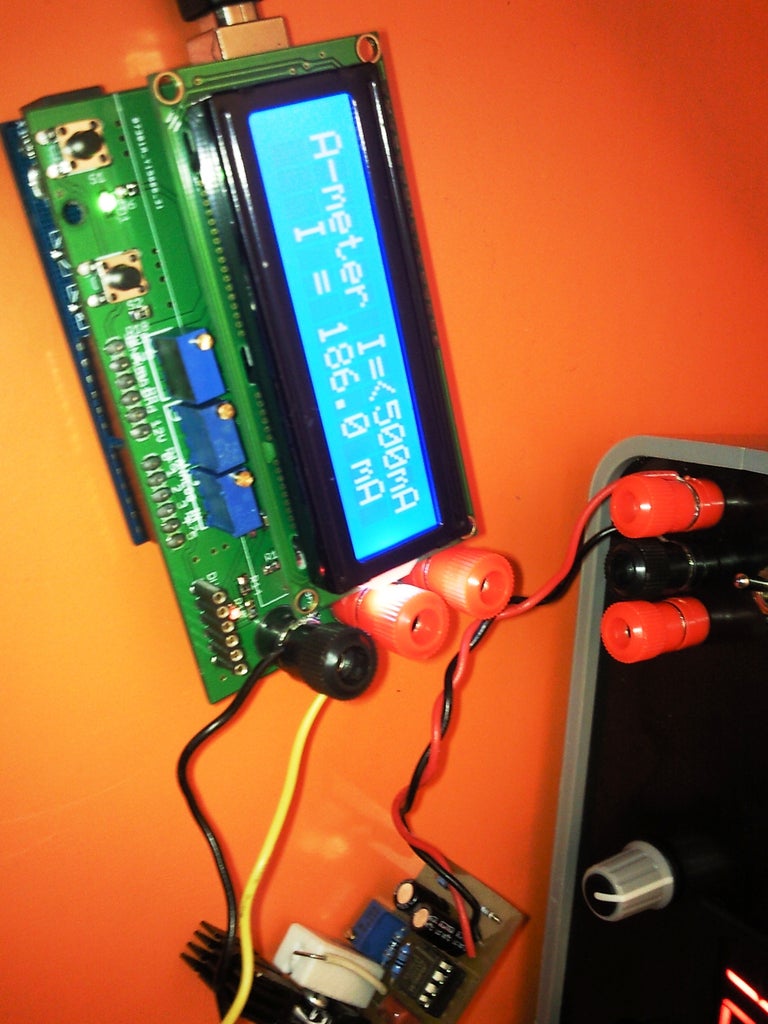
Let us trim the ampere meter.
The voltmeter trimming was easy - the error was caused only by the spread of the resistor values in the voltage dividers.
In the ampere meter the sources of errors are mainly:
- the resistor spread of R1 (see the picture in step 4). Its value is 1 Ohm, and the exact value of the used device is difficult to be measured precisely
- the voltage gain of the opamp - caused mainly by the resistors R2 and R3 values spread
- The offset of the opamp Voffset. As mentioned before LM358 is not the best choice for this project ( I had one available and I have used it. That is the reason why the PCB supports also the SO08 package - not often used in our time). In the datasheet of the chip can be seen that the offset can be 7 mV. With our current to voltage transfer solution, this can introduce a constant current error of 7mA. It can happen that no current is passing, but the ampere meter shows 7mA, and vice versa : a current of 7 mA can flow and the device can show 0 mA.
All these errors must be cleaned up by the software.
As first step we have to determine the exact value of the R1 resistor. For that purpose I used a constant current generator.
I have applied 189.9 mA input current and I have measured 186.7 mV on the resistor R1. Its value is calculated to be 0.98315 Ohm. This number will be used also as correction coefficient.
Now remain two other parameter, which must be calculated / measured : the real voltage gain of the opamp and its offset voltage.
To determine them we need to make two separate measurements at two different currents. The measurements are : we fix the current by the current generator and we measure it once with the standard DMM and once with "Arduino" based DMM. The voltage on R1 is also measured during this procedure. Here are the results which I had :
Applied current Measured current Voltage over R1
(standard DMM) "Arduino" DMM (standard DMM)
[mA] [mA] [mV]
189.9 186 186.7
73.1 71.9 71.7
The opamp offset voltage is added to the voltage drop over R1, and the resulting potential is amplified 10 (corrected with the gain error coefficient) and finally converted by the ADC.
This process can be modeled with the following equation:
( VR1+Voffset)*coeff_A_gain=Imeas;
where:
VR1 - is the voltage over R1;
Voffset - the input opamp offset voltage;
coeff_A_gain - gain error coefficient, in this case has unit of Siemens [S];
Imeas - measured by the "Arduino" DMM current
Based on this equation and the measured data, replacing Voffset with "x" andcoeff_A_gain with "y" a system of two equations and two unknown variables can be written:
(186.7 + x ) * y = 186
(71.7 + x ) * y = 71.9
186.7y + xy =186
71.7 y + xy = 71.9 ; extracting from the first the second equation
115y=114.1
y = 0.992174 - the gain error caused by the resistor value spread of the gain defining resistors R2,R3
X = 0.767 mV - the input offset of the opamp (not so bad...)
The final code for the ampere meter now would have the following definitions:
float coeff_A_gain = 0.992174;
float coeff_A_res = 0.98315;
float opamp_offset = 0.000767;
The calculation of the current can be done with the following equation:
disp_res = (((curr_value*supply )/1024 - 10*opamp_offset)/coeff_A_gain)/coeff_A_res*100;
(see the step 14 for additional information)
Step 17: Trimming the Ohmmeter


How to trim the ohmmeter I will show for the range 1000 Ohm. The same approach is used for the other range.
Before applying the software trimming some additional measurement must be done.
- The voltage drop over the Zener diode D2.
- To have stable current I have changed the following row in the main program ( loop () ) : digitalWrite(curr_mode, LOW------------------->HIGH); - in this way I can keep the current stable and to measure it during the welcome procedure. The current flowing from the PNP/PMOS collector/drain terminal to ground should be measured (picture 1)
- The same current is measured again but with serial connected resistance of 1KOhm (the max for the range) - picture 2. The voltage over the resistor should be measured too.
I have measured 2.5 mA in the first and 2.48 mA in the second measurements. My resistor was 997 Ohm.
Now we need to process the sampled data. To be able to make this we need to calculate also the Vce/Vds - the voltage drop over the transistor for bot cases.
This voltage - for simplicity I will write Vce is calculated using the following formula:
Vce = Vsupply - Vzener - Vr, where
Vsupply is the measured supply voltage of the "Arduino" board;
Vzener - the voltage drop over D2 (measured at step 1 above);
Vr - the voltage over the resistor - measured at step 3. For the first case is 0 V.
The calculated Vce and the corresponding currents are filled in excel file.(picture 3). Graph is done, and trendline corresponding to the date is shown (straight line). The equation of the trendline is displayed - it will be used for the calculations.
In my case Ir = Ice = 0.0081*Vce+2.4773 - using this formula we can calculate always the current Ice flowing through the measured resistor and also function of the voltage over the resistor, which is sampled by the ADC. Here is taken the presumption, that the dependence Ice of Vce is linear, what is commonly true.
Finally we calculate the resistance using the Ohm formula:
R = Vr / Ir
here is how the modified code looks like:
.......
float V_zener = 2.16;
float Vr = 0;
float Vce = 0;
float Ice = 0;
float coeff_v100 = 1.01;
float coeff_v30 = 1.011;
float coeff_v10 = 1.018;
float coeff_A_gain = 0.992174;
float coeff_A_res = 0.98315;
float opamp_offset = 0.000767;
volatile unsigned long last_millis = 0;
void R_1000() {
digitalWrite(curr_mode, HIGH);
delay(20);
lcd.clear();
lcd.print("Ohmmeter R=<1000");
Serial.println("* Ohmmeter mode - Range 0 - 1000 Ohm *");
lcd.setCursor(0, 1);
acc_value = 0;
for (int i=0; i <= 15; i++)
{ curr_value = analogRead(A2);
acc_value = acc_value + curr_value; }
curr_value = int(acc_value/16);
if (curr_value >= 513) { meas_overflow(); }
else { Vr = ( curr_value*supply )/1024;
Vce = supply - V_zener - Vr; Ice = 0.0081*Vce + 2.4773;
disp_res = Vr / Ice * 1000;
lcd.print(" R = ");
lcd.print(disp_res, 1);
lcd.print(" Ohm");
Serial.print("* R = ");
Serial.print(disp_res, 1);
Serial.println(" Ohm");
delay(250); }
}
As conclusion:
The presented multimeter is designed in the simplest way, trying to embed as much functions as possible. This approach brings some undesired features - the input resistance is very low, the accuracy in comparison with the standard fabric DMM is lower. The reasons for that are :
the matching of the discrete elements (mainly resistors);
not enough accuracy of the microcontroller ADC - it is 10 bit, but allows error of 3-4 LSB;
the digital noise affecting the analog measurements;
not well fixed supply voltage (it can vary when the DMM is connected to different computers), which serves as voltage reference for the ADC converter;
...etc.
Despite all disadvantages, in this work was shown, how using software tricks, the accuracy of such device can be drastically increased - starting with multiple ADC readings, their averaging and all additional software trimming. I think that similar project would be interesting for students willing to get deep inside the data measuring and processing theory. It can be used also as DMM replacement for home electronic projects, which do net require more complicated measurement tools.
P.S. Now I have added more functionality. Which you can find here
Thank you for the attention!

Participated in the
Arduino Contest


