Introduction: Arduino - Ultrasonic Sensor With LED's and Buzzer


What’s this project about?
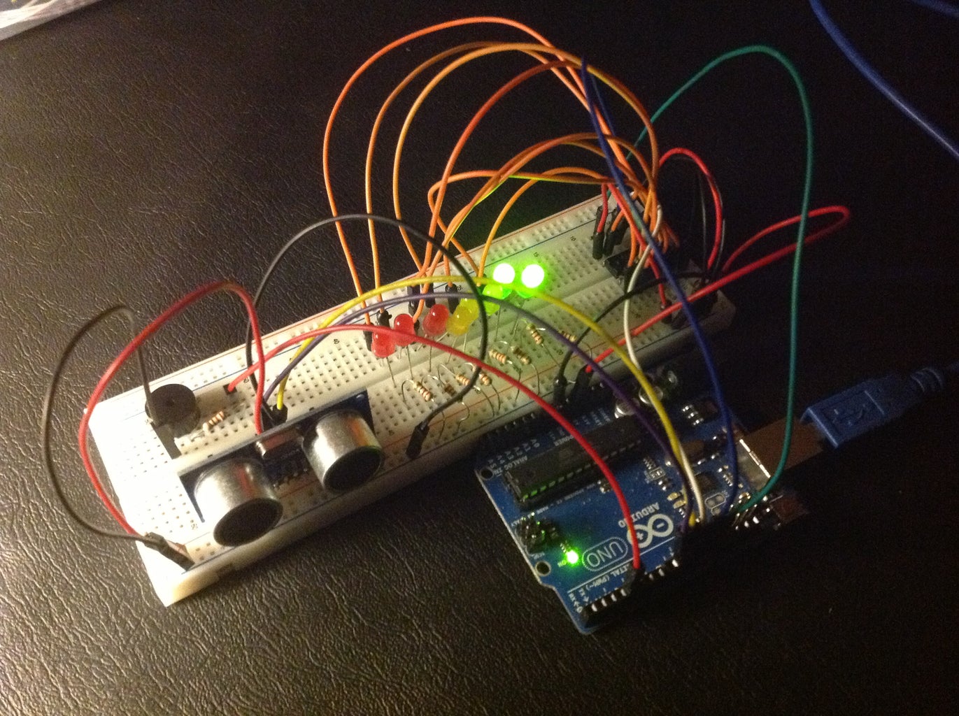
Basically we have an Ultrasonic sensor that measures the distance and the LED’s bar graph will light up according to our distance from the sensor and as we get closer the buzzer beeps in a different way. This circuit can work as a parking sensor! It's easy and cheap.
Check my website for more electronic projects and information.
Check this video to watch the circuit working
Thanks!
Parts Required:
1x Arduino
1x 74HC595 8 Bit Shift Register
1x Breadboard
8x LED’s (for example: 3x red, 3x yellow, 2x green)
9x 220 Ohm Resisters
1x Buzzer
1x Ultrasonic Sensor (for exemple: HC-SR04)
Jumper Wires
Step 1: Let's Start
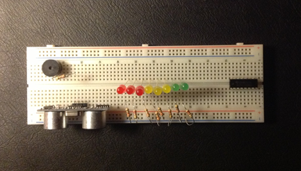
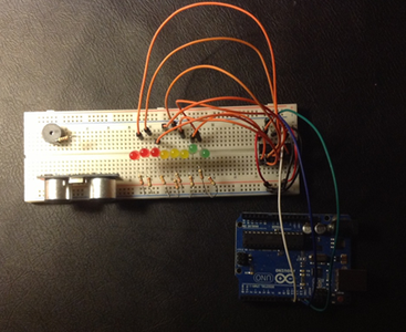
First you should place all the components on the breadboard, check the picture.
Step 2: Wires...

Wire connection: 74HC595 8 Bit Shift Register
Ground (black wire) – Pin 8 and Pin 13
5V (red wire) – Pin 10 and Pin 16
IC Pin 11 (white wire) - Arduino Pin 11
IC Pin 12 (blue wire) – Arduino Pin 12
IC Pin 14 (gree wire)– Arduino Pin 13
1st LED (orange wire) – IC Pin 15
2nd LED (orange wire) to 8th LED – IC Pin 1 to IC Pin 8
Note this connections to the LED’s must be to their positive lead (this means the longer one)
Wire connection: LED’s
Now to the negative lead use one resistor per led and connect them to the ground (black wires)
Step 3: More Wires...

Wire connection: Ultrasonic Sensor: HC-SR04
VCC (red wire) – 5V
Trig (violet wire) – Arduino Pin 9
Echo (yellow wire) – Arduino Pin 10
Ground (black wire) –GND
Wire connection: Buzzer
Shorter lead (black wire) – ground
Longer lead (resistor in series, red wire) – Arduino Pin 4
Step 4: Programing
Now upload this code:
/*
* IRremote Library - Copyright 2009 Ken Shirriff
* created by Rui Santos, http://randomnerdtutorials.wordpress.com
* Ultrasonic sensor with LED's and Buzzer
* 2013
*/
int tonePin = 4; //Tone - Red Jumper
int trigPin = 9; //Trig - violet Jumper
int echoPin = 10; //Echo - yellow Jumper
int clockPin = 11; //IC Pin 11 - white Jumper
int latchPin = 12; //IC Pin 12 - Blue Jumper
int dataPin = 13; //IC Pin 14 - Green Jumper
byte possible_patterns[9] = {
B00000000,
B00000001,
B00000011,
B00000111,
B00001111,
B00011111,
B00111111,
B01111111,
B11111111,
};
int proximity=0;
int duration;
int distance;
void setup() {
//Serial Port
Serial.begin (9600);
pinMode(trigPin, OUTPUT);
pinMode(echoPin, INPUT);
pinMode(clockPin, OUTPUT);
pinMode(latchPin, OUTPUT);
pinMode(dataPin, OUTPUT);
pinMode(tonePin, OUTPUT);
}
void loop() {
digitalWrite(latchPin, LOW);
digitalWrite(trigPin, HIGH);
delayMicroseconds(1000);
digitalWrite(trigPin, LOW);
duration = pulseIn(echoPin, HIGH);
distance = (duration/2) / 29.1;
/*if (distance >= 45 || distance <= 0){
Serial.println("Out of range");
}
else {
Serial.print(distance);
Serial.println(" cm");
}*/
proximity=map(distance, 0, 45, 8, 0);
//Serial.println(proximity);
if (proximity <= 0){
proximity=0;
}
else if (proximity >= 3 && proximity <= 4){
tone(tonePin, 200000, 200);
}
else if (proximity >= 5 && proximity <= 6){
tone(tonePin,5000, 200);
}
else if (proximity >= 7 && proximity <= 8){
tone(tonePin, 1000, 200);
}
shiftOut(dataPin, clockPin, MSBFIRST, possible_patterns[proximity]);
digitalWrite(latchPin, HIGH);
delay(600);
noTone(tonePin);
}
Step 5: That's the Final Product.