

Introduction: Driving RGB LED Strips Off an Arduino
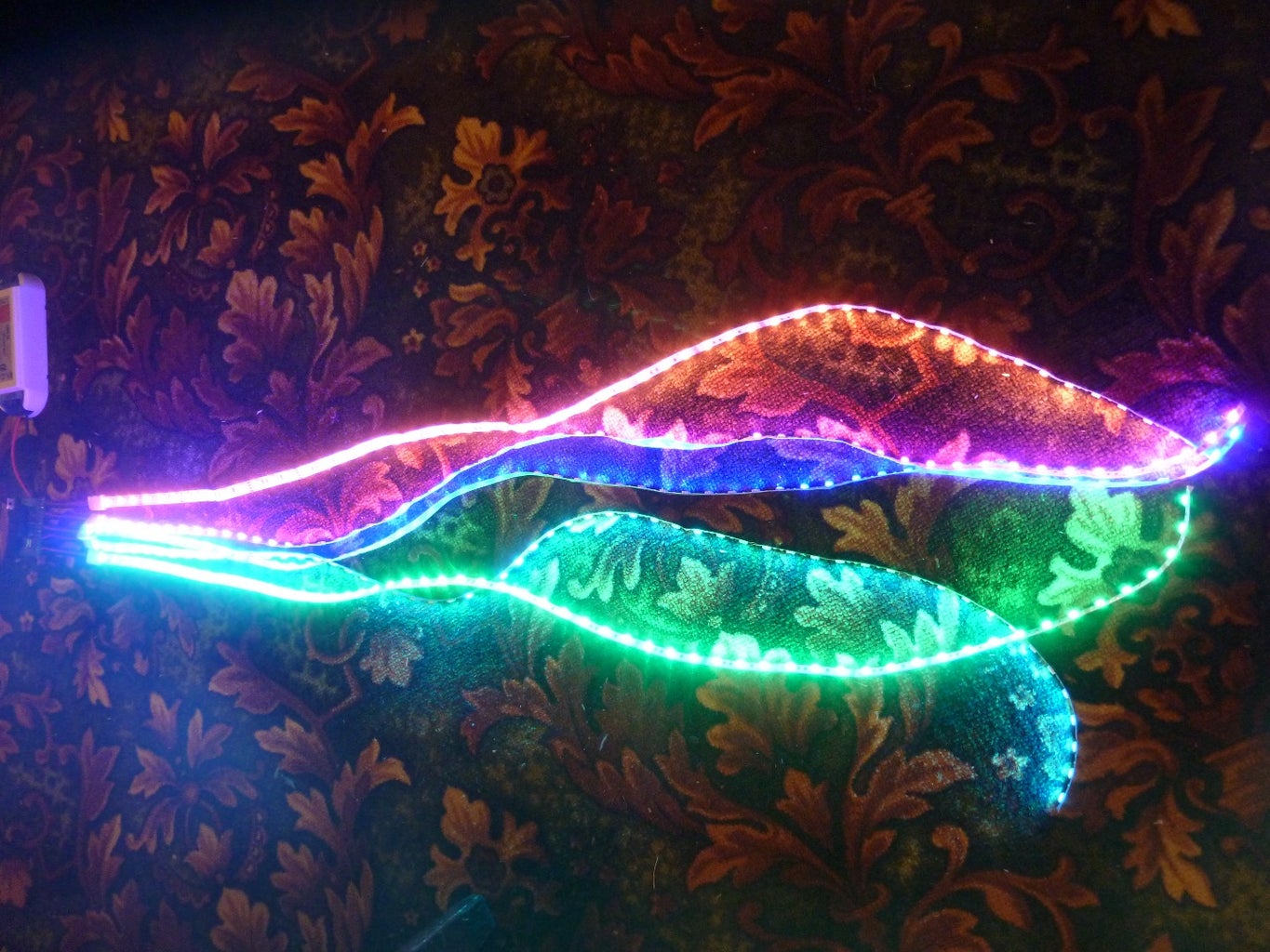


Christmas is coming and you may be wondering how to make it colorful and bright with an Arduino and an RGB LED strip. At least, that was exactly what I did a year ago and wasn’t able to find any clear and simple instruction anywhere. With this instructable I will try to correct that sad omission.
At this point you should have an Arduino board and 5 meters of an RGB LED strip with its power supply on your hands. As the Arduino has 6 PWM outputs let’s assume that you intend to use them fully, so have cut the strip into two 2.5 meter pieces.
Depending on which way you chose, you’ll need some additional hardware, as described in the steps below. Onward!
Step 1: Power Supply

Before we start connecting the Arduino to a LED strip, let’s deal with the power source. LED strip is usually run off 12 volts, Arduino works on 5 volts. Most Arduinos have a Vin pin that can be connected to bigger voltages, with 9 volts recommended and 12 volts a safe maximum that, according to some, should be generally avoided. Considering that a LED strip power supply usually provides a bit more than nominal 12 volts (something like 12.3 in fact), you may be tempted to avoid connecting it to Arduino.
However, if you check the specs of a voltage regulator onboard your Arduino (it’s a variation of a 1117 5v regulator) you’ll see that it is perfectly capable of dealing with 12 volts. Its power rating usually states 20 volts as a maximum (such as the MC33269 from ON Semiconductor that is installed on most genuine Arduinos), some models have a 15 volts restriction (such as the AMS1117 5.0 found on most Nano clones), but almost never less (one exception I found is Torex XB1117 that has a rating of 10 volts, but you won’t see it on a Duino board, genuine or not). In any case, if in doubt, you may check this instructable to find out more about the voltage regulator. On a Nano it sits on the back, but is easily recognizable.
So, it’s perfectly safe to connect everything to one 12v supply: the LED strip directly, the Arduino via its Vin pin (don’t use the power jack; the strips +12V line MUST be connected directly to the power supply). There’s one thing however that you should be aware of: the heat. Voltage regulators tend to heat a lot and their heatsink has a rather small footprint, so it’s better to check its temperature after some working time, to be on the safe side.
You may also connect the Arduino to 5v and the power line of the LED strip to 12 volts. It will also work, juts don’t forget to connect the grounds from both sources together.
It is a good idea to add a master MOSFET to the 12v circuit to be able to disconnect the LED strip without disconnecting the power (say, with an IR remote).
Step 2: N-Channel MOSFETs
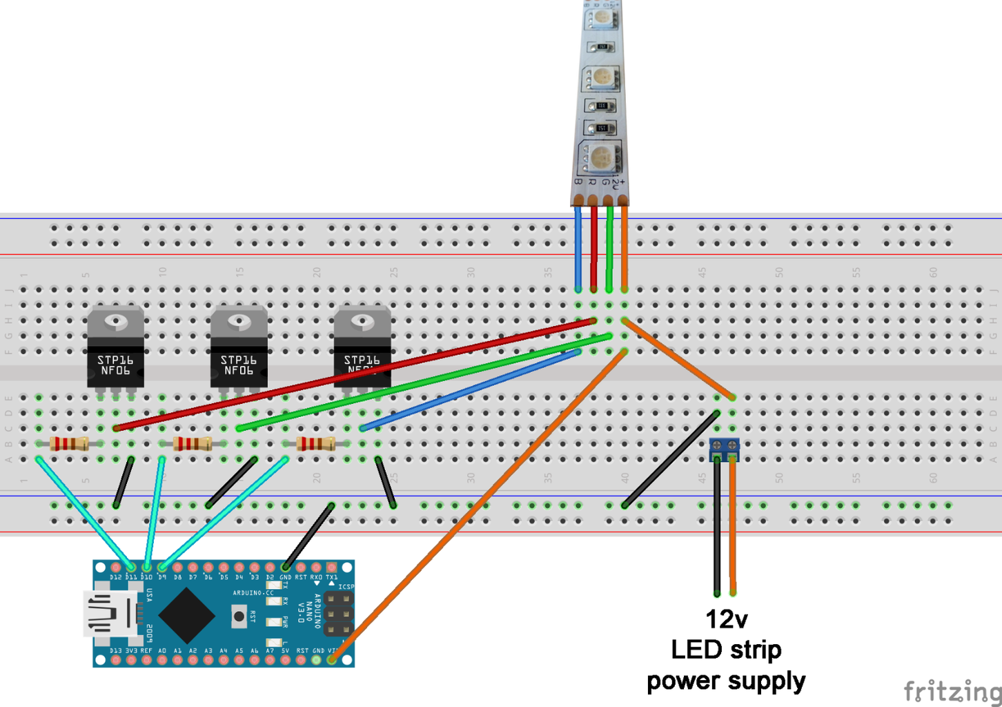
The most obvious way of connecting LED strips to an Arduino is using N-Channel MOSFETs. There are tons of tutorial on their use, like this one. The N-Channel MOSFET is ideal for our purpose, because it sinks current, is placed after the load, so the connection is extremely simple: Source to Ground, Gate to Arduino pin, Drain to a color channel of the LED strip (usually a colored wire). A resistor of 220 Ohm is recommended between the Arduino pin and Gate, but is not strictly necessary. Now you can control the LED strip the same way you blinked a LED on a breadboard.
Which MOSFET to use? As we’re dealing with to220 package here, they’re all pretty powerful. However, some are made to handle high voltages (1000V and more) and some are good with high currents (200A and up). You won’t need high voltages, so aim at one that works with at least 20 Volts and 6 Amps. In fact, you’ll probably end up with something like 55V/41A, as these are common and could be useful in your other projects.
This method is quick and easy, but has a downside: you’ll need 6 MOSFETs for 2 pieces of LED strip, and they are bulky, sometimes costly and basically a bit of overdrive, as their power rating usually is way more than you need (like 55V/41A). You may also find this too obvious and want to make something more interesting. Ok, on to the next step.
Step 3: Darlington Transistor Arrays
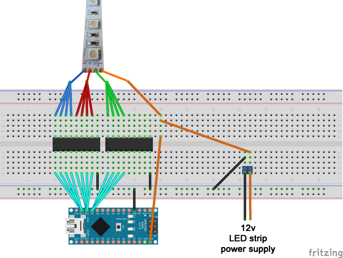
An excellent alternative to MOSFET is a cheap Darlington transistor array like ULN2003. In short, this chip is a bunch of transistors stacked together in one convenient package (DIP included, so it’s easy to use them on a breadboard). Each transistor pair on a Darlington has a power rating of 500mA, but they can be paralleled for bigger currents.
Darlington arrays usually come in two packages: 7-pair and 8-pair. The second is obviously better for our projects (and costs the same). For two 2.5 meter strips, we’ll need at least three such 8-pair arrays as we’ll want to parallel 4 pairs on one color channel of the LED strip, achieving a power rating of 2A. Why so much, if, according to the LED strip datasheet, it should consume 3A in total for a 2.5-meter piece?
UPDATE: I fell for the common mistake here, that is, considering Amps a constant and not relying on Ohms Law. The LED power consumption of 20mA is correct for its nominal voltage, around 3V. If we're powering it with a 12V power supply we can effectively divide this power consumption by 4 (or by 3 if using a 9V supply). So, just to be on the safe side, we can assume that each LED consumes 6mA from a 12V supply, which means 1.8A per color on a 5m strip; it's 2.4A for a 9V supply. So it is possible to get away with only 2 pairs per color in parallel for a 2.5 meters and 4 pairs for a full strip. Still, you can't go wrong with excess safety, and Darlingtons are cheap, so there's no need to actually reduce their numbers unless you're short of space.
Because a power rating of a RGB LED strip deals with its overall consumption. RGB LED strips are intended for decoration, not illumination; it is not intended to be turned fully on, producing bright white light (in fact, a LED strip is supposed to be connected to a controller that restricts its power usage). However, individual colors, say, green, can be turned fully on. Considering that we have 60 LEDs per meter of the strip, and each LED is consuming around 20mA, it’s easy to see that a full-on single color will need 1.2A per meter, or 6A for a 5m strip.
Why, then, only 4 pairs and not 6 (that will fully cover 3A)? Because we are essentially building a LED strip controller on an Arduino and can restrict the current by not turning any single color to full brightness for a long time (short bursts are ok). However, you may want to use all 6 pairs to be on the safe side. That’s the reason for ‘at least’ up there.
The wiring of a Darlington array is extremely simple and obvious, as an input pin and a control pin are facing each other (see the picture above). And yes, it needs only ground connection, no voltage.
This covers the basics and is enough to get your Christmas lights running.
Step 4: The RGB Amplifier


Essentials over, story mode on. My wife presented me with an Arduino (I think she regrets it now) last autumn. I blinked and I buzzed and then decided to return the favor in form of a Christmas decoration. As I was totally inexperienced then, knew absolutely nothing about electric stuff, I went to Instructables and found this (WARNING: read the WARNING there!). A year ago there was no WARNING in the article, so I ordered a bunch of RGB amplifiers and actually made this stuff as described there. And it worked, and the wife was happy, and we had cool illuminated holidays. Yes, there were glitches and yes, I fried one pin on an Arduino, but that last bit came later when I was experimenting.
I suspected something is not exactly right with this solution, but I was inexperienced, in a hurry, and actually ordered a bunch of cheap Chinese Nano clones with the amplifiers, so please don’t judge me harshly.
Also don’t discard the amplifiers: properly cooked, they are pretty useful, as you’ll see.
Gone Christmas I decided to dig a bit deeper into the amplifiers theme. Most notably, I didn’t like the aforementioned glitches: the contraption sometimes went into an infinite reboot loop, and I was pretty sure it was hardware problem, not software. Not only did I fry a pin, I also dissected an amplifier to learn how it worked. And everything became clear.
See the picture above. On the output end of an amplifier there are three N-channel MOSFETs, as described in step 2 of this instructable. Next to them sits a logic-inverting chip that provides voltage to the gate of the mosfet when there’s nothing on its respective input and vice versa. The amplifier works pretty simply: it tries to sink voltage (without any load) via each input channel. If it sinks (the respective channel is grounded, meaning the LEDs are on), nothing goes to the inverting chip, so it provides voltage to the MOSFET gate, which in turn opens the output channel. If not, the voltage goes to the invertor, closing the MOSFET.
Now, the amplifier is connected to 12v power supply. It doesn’t have any voltage regulator (what for? It thinks it is connected to another LED strip!), so, being connected to an Arduino, it grounds 12v in an Arduino pin that is limited to 5v. Which is obviously bad, even if Arduino may sustain such a treatment (or may not).
That is why the method described in the WARNING instructable is wrong.
But there’s a bright side. Note that an amplifier sinks 12 volts with no load in it. Which means that almost any transistor on the other end will do, it doesn’t have to deal with high Amps, just with 12 volts. So if you connect RGB amplifiers to a Darlington array, you won’t need to parallel its transistor pairs, meaning a single Darlington will easily handle two RGB strips connected via amplifiers. And that’s how my LED strips are working this Christmas, by the way.
And there’s more!
You can connect RGB amplifiers to LED drivers like the TLC5940, thus increasing the number of connected RGB strips almost indefinitely! Well, at least to 5 with one driver. In any case, the LED driver is a current sink device capable of dealing with 12 volts, but not a lot of Amps. The amplifier sinks 12 volts with no Amps in it, thus producing an ideal combo. The connection if straightforward – color channels from an amplifier go to output pins of a driver, and that’s it. You may read more on the LED drivers in my other instructable.
Step 5: Making Your Own Board to Run 5 RGB LED Strips


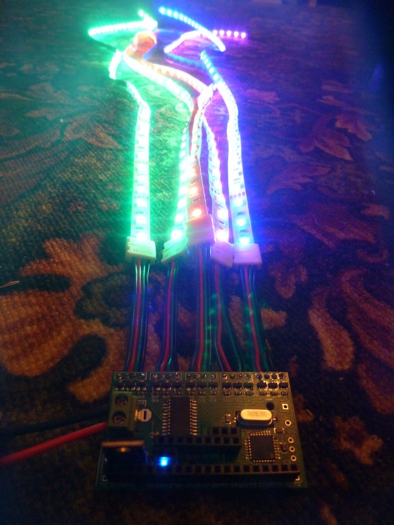
After dissecting an amplifier and playing around with LED drivers I decided to make an Arduino-like board capable of controlling 5 RGB strips (or more with additional boards attached). As I was ordering some other PCBs from the fab and had place on a 10x10cm default plate, I included the first prototype in there. And it was wrong, so I had to make a second one. This ‘bonus’ step may help some of you avoid my errors.
The board design is pretty simple: it has an Atmega328 chip, a LED driver (DM633 in my case), a 1117 5.0 voltage regulator and 15 N-Channel MOSFETs on 5 RGB outputs. Unlike an RGB amplifier, this board doesn’t have any logic-inverting chips, so the logic is inverted in software (namely, 0 means full on and maximum value means off). The MOSFETs gates go to LED driver outputs and are pulled up to 5v by 10K resistors, so they keep the current flowing when the driver is closed and stop doing it when the driver output opens, sinking current.
Which leads to the first important thing: there must be a powerful master MOSFET on such a board that will keep the power to the strips off when it’s not needed there. That is, while the device boots up. If there’s no such MOSFET installed, all the LEDs on all connected strips will turn fully on the moment the power is connected (as the driver keeps outputs off by default, but we have the logic inverted). And this will lead to extreme power consumption and possible death of the power supply unit or something of the like.
Secondly, the voltage regulator (in SOT-223 package) must have its heatsinking bump properly connected or it will heat a lot. And the aforementioned bump is NOT the ground, as one would think, but output. I didn’t check the datasheet and my ‘logic’ failed me here, don’t repeat that mistake. I even made a big heat sinking zone on my version 2 board, but that’s not needed.
The rest is pretty straightforward here.
And that’s it! Please feel free to ask any questions!

Participated in the
Make It Glow! Contest


