

Introduction: Dry Cell Electrolyser


An electrolyser is a piece of scientific equipment that splits polarised molecules into its ions. In this case it will split water into hydrogen and oxygen gas. A dry cell electrolyser is an electrolyser that is completely enclosed; the other type is a wet cell electrolyser which can be two metal plates in a bowl of water. The equipment is fairly simple but the theory behind it is a bit more complicated, if you’re not interested in the theory then skip to step 1.
Here’s the theory: the electrolyser uses the different ionic charge on the different atoms in the molecule to split it into its respective charged atoms or molecules, for example, water gets split into Hydrogen and Oxygen because in the water molecule the hydrogen is slightly positively charged and the oxygen is slightly negatively charged. These charges are only very slight, +1 electron volt (ev) for each hydrogen and -2 ev on each oxygen atom. Just for comparison 1 electron volt is 1.6×10⁻¹⁹ Coulombs (c) and 1 Coulomb is the charge transported by a steady current of one ampere in one second. The hydrogen is attracted to the negatively charged electrode or Cathode and the oxygen is attracted to the positively charged electrodes or Anodes. At the anodes the oxygen ions loose an electron and bond to form oxygen gas, at the cathodes the hydrogen ions get an electron from the cathode and then bond to form hydrogen gas. This transfer of electrons from and to the electrodes completes the circuit and allows current to flow. A catalyst can be used to make the process more efficient by reducing the energy needed to start the process; the catalyst that I use is sodiumhydroxide in a 1 to 40 mix with deionized water. The water doesn’t need to be deionized but it extends the lifetime of the unit as minerals and other stuff won’t build up on the electrodes.
Step 1: Parts and Tools

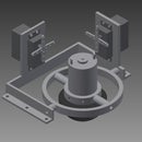
The PDF shows the parts of the electrolyser and how they're assembled, however I will go into this in more detail later.
There are several parts and a few tools that you will need.
10mm polycarbonate
8mm id 12mm od rubber tubing
3mm rubber gasket material
180cm M8 studding
18x M8 dome nuts
18x M8 nilock nuts
4x 1/4in BSP aluminium washers
2x 1/4in BSP male to male adapter
2x 1/4in BSP male to 1/8in BSP female adapter
2x 1/8in BSP to 8mm tube connector
2x 1/4in BSP 2 way ball valve
12AWG wire
17x M7 ring terminal
15x Flag crimps
Loctite pipe sealant or equivalent
13mm spanners
Drill
Crimp tool
Wire cutters
Wire strippers
Jig saw
Permanent marker
Metal ruler
Sharp knife
Attachments

Step 2: Polycarbonate End Walls

I made the end walls out of polycarbonate as I had some laying around and it is a strong material that is actually used to make blast and bullet proof screens. I designed the end plates according to the amount of polycarbonate that I had but there inst really any limits, the end walls are 240X200mm. The end walls contain 18 8.5mm holes that allow clearance for M8 Bolts and a 11.4mm hole with a 1/4in BSP thread taped into it. The threaded hole is for the valves and the hose tails. The 8.5mm hole centres are 14mm away from the edge of the of the plate and are 42.4mm horizontal and 43mm vertically spaced, the 1/4in BSP threaded hole is 42mm away from the top left corner horizontally and vertically. There is a PDF copy of the drawing attached bellow, I used Autodesk Inventor to design the plates as I got it free as a student from the Autodesk website.
Attachments
Step 3: Electrodes

The electrodes are made of 0.7mm thick 304 grade stainless steel as it is pretty stable and unreactive, the best material would be gold but that would cost far to much. There are two different designs the only difference is the location of a 3mm hole, this hole allows the water and electrolyte to equalise in the cells of the electrolyser and the bigger holes allow the gases out and are in line with the 1/4in BSP holes in the end walls. Both plates are 200x160mm, as this fits tightly between the bolts with the rubber over them, and have a tag in the middle at the top that is 6.5x10mm and is for a flag connector for powering the electrolyser. The equalising holes are small to increase efficiency and is located 20mm from the corner. The 10mm hole is located 22mm from the corner. Bellow are the drawings for both of the plates, you can either cut them out yourself or get them made for you.
Step 4: Gaskets

I made the 16 gaskets from clear PVC and bought it in the form a of walk-in freezer curtain strip measuring 200x3000x3mm this cost about £20 from eBay. I bought the PVC in the form of a walk-in freezer curtain as it was the correct width and therefore reduced the amount cutting necessary. The Gaskets are 200x160mm with a 136x176mm cut out with 6x6mm chamfered corners (see PDF bellow).
Attachments
Step 5: Nuts, Bolts and Main Assembly


You will need to cut 18 100mm lengths of M8 studding and file the ends so a nut fits on easily, on one end of each of the 18 bits of studding put a dome nut and a washer and then feed them through the 18 holes in one of the end walls. Next cut the rubber tubing into 18 lengths of 57mm and put them over the studding as insulation. Next put one of the gaskets in between the bolts and the rubber tubing and then put an A plate, a gasket, a B plate, a gasket, an A plate... on top until you have used the 16 gaskets, 8 A pates and 7 B plates ensuring that the 10mm holes line up with the 1/4in BSP hole in the end walls. Once all the plates and gaskets are on put the second end wall on top and then put the washers on the studding and the nilocks on tightening the corners first and then the others.
Step 6: Valve Assembily

Finally the end is within sight, this bit is fairly simple, first you put a 1/4in BSP aluminium washer on the 1/4in BSP male to male adapter and then put Loctite on the thread and screw it into the 1/4in BSP 2 way ball valve and tighten. On the other side of the valve Loctite and screw in the 1/4in BSP male to 1/8in BSP female adapter and then the 1/8in BSP to 8mm tube connector into that. the other 1/4in BSP aluminium washer goes on the other end on the 1/4in BSP male to male adapter which you MUST NOT put Loctite on as it will make polycarbonate or plastic brittle, repeat this once. Screw these assembles into the end walls.
Attachments
Step 7: Wire It Up

This is the final part of construction, cut the 12AWG wire into 15 100mm lengths and cut the rest in half strip about 8mm from each end of the lengths of cable and crimp a ring terminal onto one end of all of the lengths of the cable and on the other end of the short cables crimp a flag terminal and on the other end of the long cables strip about 15mm and you can tin this using a soldering ion but this isn't necessary. Penultimately on each of the tabs on the electrodes put one of the short cables using the blue flag terminals. Finally using M6 bolts connect the M7 terminals together on each side and one of the longer cables on each side.
Step 8: Running the Electrolyser
Fill the electrolyser to just below the 10mm holes with a 40 to 1 mixture of water, preferably distilled, and 0.1 mole sodium hydroxide. Next connect some more of the orange rubber tube to one of the hose tails and the other end to some form of storage, eg plastic bag. Finally connect the cables to a car battery or high current power supply capable of supplying 12 volts and more than 20 amps. You should find that the bag fills with hydrogen and oxygen gas, this gas can be used as a fuel for cooking or in an engine as it is highly flammable and when you burn it it produces water again so its environmentally friendly.

First Prize in the
Off the Grid Contest

Participated in the
Hurricane Lasers Contest


