

Introduction: Dual Voltage Regulated Power Supply for Arduino/microcontroller Projects


About a couple of months ago when I first had my hands on Arduino Uno, I had no idea where does that 3.3V power next to the 5V pin comes from, or more accurately, I did not really think about it until I had to make my own versions of standalone Arduinos/ATmega projects. I needed 3.3V source in addition to the regular 5V for driving some of the components. I soon realized that ATmega microcontroller does not provide a 3.3V output from any of its pins as a dedicated power source, I must create it through power circuit design. So here is my humble design. There are tons of similar materials available on the Internet. I read many of them and the datasheets, and put my understanding together in my own way, to suit my own purpose. I am sharing it here in a hope that someone as novice as myself can perhaps use it readily.
Step 1: Material Needed

1) Strip board, I took a 24 strip board
2) 1 Terminal block (I took a
screw terminal)
3) 1 Switch
4) 3 Electrolytic capacitors (recommended
two 10uF and one 1uF, but I have used all 10uF)
5) 2 Resistors (R1 & R2,
where the R2/R1 ratio should be nearly 1.64. I have used R1=1k and R2=1.5k
instead of 1.64k. This is why I shall get 3.13V, not 3.3V. You can use a calculator like this)
6) 2 pin Male header (optional)
7) LM7805 5V voltage regulator IC
8) LM317 3.3V voltage regulator
IC
Step 2: Design

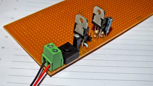
Here goes my strip board design showing placement of the components. On the right hand side of the picture I have included a strip board friendly schematic diagram, and the actual aerial photograph after assembly.
Step 3: Fabrication


I hope anyone can follow the above design for placing and soldering components. Remember to cut the strips in indicated locations (there are only 3), and use jumper wires as indicated (there are only 2, in fact the one at the top can be achieved by solder). Advice for novices: Start from the terminal block and proceed to the top. Make sure to check continuity and lack thereof using a multi-meter after soldering every step; and don't proceed to the next step if continuity and short check fails at any step.
Step 4: Special Provisions

Note that I have placed a two-pin male header after the LM7805 circuit, so that I can draw a regulated 5V power from these pins for anything else outside my board, or supply 5V to the board from a regulated power source like mobile phone/tablet chargers and wall warts, if I need so. I can also use these pins to attach a LED to indicate power, I don't like my boards to have a constantly lit/permanent power indicator.
Step 5: Notes
This design provides me with a clean regulated 5V, 3.3V (depending on R2/R1 ratio) and GND rails. It takes 4 strips from my board, and I am still left with 20 strips, adequate for placing an ATmega328 or other MCU and more.


