

Introduction: EEZYbotARM Mk2 - 3D Printed Robot


This is a four axis 3D printed robotic Arm.
It follows the success of my previous smaller one: the EEZYbotARM so I simply called it MK2 (make 2). It is a little bigger and stronger, just to obtain more payload and increase reach.
I implemented also some little features like: a replaceable gripper with quick coupler, internal cable routing in main big arms and the vertical axis supported by spheres.
It has been designed without a definite purpose, the aim is educational, providing a suitable hardware that allow to concentrate on exploring all its potential applications.
Following the requests of many users I made available the whole project on my Onshape account. You can find the source CADfiles at this link EEZYbotARM mk2. You can copy and modify the files, designing your own version. Please follow the original licence and provide attributions.
EEZYbotARM Mk2 has been initially released on my Thingiverse account here: thing 1454048
You can find a dedicated instructable of the smaller mk1 at this link :EEZYbotARM instructable
You can find more DIY projects at my personal web page www.eezyrobots.it
Step 1: NOTES


3D PRINTING :
It is a little more challenging to print than the mk1 due to its dimensions and also some parts geometry.
Some few components (like main horizontal arm 006) requires supports enabled and a printing area of 200x200 millimeters. I supply all stl models already correctly oriented to avoid supports when possible.
I printed all the parts using a Prusai3 with ABS filament, but also PLA works great.
I made available a short video of some of the parts printing on YouTube
It has been replicated may times and you can view at Thingiverse user makes
HARDWARE :
I used metric hardware and all joints rotate on M4 screws. (in alternative of M4 an #8-32 can be used) Holes of the joints are designed quite tight. This to allow a fine adjust of their diameter using an exact drill bit.
On screws are to be used selflocking nuts. They are to be tightened till the locking of the joint, then consequently you have to loose them until you obtain a smooth movement with a low clearance between components. On the two axis of the main vertical.arm I used M4 threaded rods
SOFTWARE / FIRMWARE :
The purpose of the robot is to provide an educational tool wich allow making experiment with different control methods. I found very easy to use a Mini Maestro 12 Controller from Pololu, it is not very cheap but solve a lot of problems. You have to install drivers, a software and when connected to usb you're are immediately able to drive the servos choosing their speed and acceleration also. You can store the servo position to a sequence and when ready it can be played once or in a loop. Can also be stored in the internal script memory and it can be automatically played without computer connected. (I'm NOT sponsored by Pololu !)
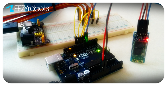
Anyway I also developed an instructable to be used on four axis servo driven robots with Arduino and an Android APP via Bluetooth. And here's the link
Step 2: Parts and Materials


Here following the list of parts necessary to built the mk2 robotic arm.
You need some 3D prinded parts and some commercial items. If you do not have a 3D printer there are several 3D printing services like 3D Hubs that can do the work for you.
Commercial items can be easy found on the web. You mainly need 3 big servos MG995 or MG946 (they are dimensionally the same, but 946 are a little more powerful). Then a small sg90servo, a 606 bearing and some steel spheres with a diameter of 6 mm. The remaining are components that can be found ol local hardware stores (remenber only that I use metric hardware)
3D PRINTED PARTS BOM list :
- EBAmk2_001_base.STL
- EBAmk2_002_mainarm.STL
- EBAmk2_003_varm.STL
- EBAmk2_004_link135.STL
- EBAmk2_005_link135angled.STL
- EBAmk2_006_horarm__.STL
- EBAmk2_006_horarm_plate.STL
- EBAmk2_007_trialink.STL
- EBAmk2_008_link147_new.STL
- EBAmk2_009_trialinkfront.STL
- EBAmk2_010_gearservo.STL
- EBAmk2_010_gearservo_22DENTI.STL
- EBAmk2_010_gearservo_25DENTI.STL
- EBAmk2_011_gearmast.STL
- EBAmk2_012_mainbase.STL
- EBAmk2_013_lower base.STL
- EBAmk2_014_claw base.STL
- EBAmk2_015_claw finger dx.STL
- EBAmk2_016_claw gear drive.STL
- EBAmk2_017_claw finger sx.STL
- EBAmk2_018_claw gear driven.STL
- EBAmk2_019_drive cover.STL
NON PRINTED PARTS BOM list :
- 3 - 955 or 946 servo
- 1 - SG90 SERVO
- 1 - M6 selflocking nut
- 1 - M6x25 screw
- 2 - M3 selflocking nuts
- 2 - M3 x 20 screws
- 1 - M3 x 10 hex recessed head screw
- 9 - M4 selflocking nuts
- 1 - M4 x 40 screw
- 1 - M4 x 30 screw
- 5 - M4 x 20 screw
- 1 - M4 x 60mm threaded rod
- 1 - M4 x 32mm threaded rod
- 25 - dia 6 mm ball spheres
- 1 - 606zz bearing
- some M4 washers
Attachments

Step 3: Assembling the Main Base


Let's start assembling the main basefollowing the steps :
A - Put in position an MG946 servo with the driving shaft aligned forward. Fix the servo to the main base using the selftapping screws supplied with it.
B - Insert 3 M3 nuts in the receptacles of the main base as swown.
C - Insert the 606 bearings in its housing and attach the plate to the main base using 3 M3 screws. Verify the freedom of movement of the bearing.
D - Position the drive plate on the splined shaft and upper the driving printed gear. Add one or two small selftapping screw to connect plate and the gear. ( There are two driving gears available one has 22 teeth and the other 25. I
made two because during printing of the base I've got some deformation and the two axis distance became smaller )
E - Fill the path using about 25 spheres with a diameter of 6mm.
F - Insert an M6 self locking nut in the receptacle of the swivel base then place in position le geared base and fix it using a couple of M3 screws and nuts as shown.
G - Keeping the main base flat and the swivel element in contact with it, connect the two elements using an M6 screw.
Step 4: Assembling the Main Arms


H - Now the main base is finished.
I - Put in position the main arm and the vertical drive lever, connect them
with the main base horizontal axis using a 4mm dia rod 33 mm long.
J - Fix in position the two servo and hold in place using eight selftapping screws. To drive the arms use the sigle horns supplied with the servos. Make sure that the mid position of the servos are aligned with the housing of the arms
K - Connect the lower end of straight lever to the driving arm.
L - Connect the lower end of angled lever to the fixed end on the base.
M - Use a threated M4 rod to connect the horizontal arm and the triangle to the upper part of the main arm.
N - Connect the straight rod to the main arm and angled to the triangle.
Step 5: Assembling the Gripper


O - Attach the rod and the fast release of the gripper, to the front part of the horizontal arm.
P - The robotic arm is now assembled.
You can now proceed with the gripper assembly or you can use your own gripper design
Q - Assembly the gripper as shown in the image "Q".
R - Attach the gripper to the fast release at the end of the arm and make the servo wire pass in the internal space of the horizontal arm.
Collect all the wires on the rear side of the robot leaving enough freedom of movements expecially on the rotation of vertical axis.
The eezybotarm mk2 is now mechanically assembled, ready to be driven by the electronics.
Step 6: Control


The way to drive the servos of the robotic arm, are several.
As told at the beginning, I found very easy using a Pololu USB servo Mini Maestro The controller has four different sizes (6, 12, 18,24) depending on how many servos you have to manage. I bought the size 12.
To use it you have to install drivers and then a free software (available for win & linux).
When connected to a PC with a USB cable (A to miniB) you're are immediately able to drive the servos choosing their speed and acceleration also. You can store the servo position to a sequence and when ready it can be played once or in a loop. Can also be stored in the internal script memory and it automatically played without any computer connected.
INSTALLING DRIVERS & SOFTWARE
Download the Maestro Servo Controller Windows Drivers and Software from this link (5MB)
Before connecting your Maestro to a computer you should install it's drivers.
Open the ZIP archive and run setup.exe. The installer will guide you through the steps required to install the:
Maestro drivers
Maestro Control Center
- command-line utility (UscCmd)
When finished You'll find the shortcut of control software on your desktop
Connect now the device to one of your PC USB port. The computer will detect a new hardware showing the "new hardware wizard", choose
In the next window choose "Install the software automatically” and click “Next”.
You will have three times the hardware wizard pop up, due to the different control method available. At the end you'll find in computer’s Device Manager 2 COM ports (Command Port and the TTL Port) and an USB entry.
Step 7: Software Features


THE MAESTRO CONTROL CENTER
The Maestro Control Center is a graphical tool to use the USB interface for controlling servos and setting up the maestro.
It has many tabs to
STATUS
The channel displyed follow your maestro connected (6, 12, 18, 24) is used for controlling the Maestro’s outputs and for monitoring its status in real time.
For a channel configured as a servo, the checkbox enables the output, dragging the slider adjusts the target setting of the channel, and the green ball indicates the channel’s current position.
The “Speed” and “Acceleration” inputs allow the speed and acceleration of individual servo channels to be adjusted
in real time. The default values are specified in the Settings tab, but it can be useful to adjust them here for fine-tuning.
ERRORS
The Errors tab indicates problems that the Maestro has detected while running
CHANNEL SETTINGS
The Channel Settings tab contains controls for the channel parameters that are stored on the Maestro
Each of the channels:
- may be assigned a name
- has a servo mode (default) or a Input / output mode
- pulse rate
- a min max positions
- a startup or error behaviour (off, ignore, goto position)
- speed
- acceleration
- 8 bit neutral
SEQUENCER
This tab is great, allows simple motion sequences to be created and played once or in loops.
A sequence is simply a list of “frames” specifying the positions of each of the servos and a duration (in milliseconds) for each frame. Sequences are stored in the registry of the computer and can be played or copied to the script, which is saved on the Maestro.
SCRIPT
The Script tab is where you can enter a script to be loaded into the Maestro
This are basic explanations if you need more detailed instructions a great help can be found in Pololu Maestro manual
It seems a little complicate for a non electronics expert like me, but as told, this is the easiest way I find to obtain a way to control the bot arm and experiment in real time it's movements.
Also the sequencer tab allows you in a while to obtain loops without knowing how to writes codes. I used this method to make the demo loop of the mk1 here on YouTube
Step 8: Conclusions


That's all for now
If you are looking for others methods for driving the robotic arm with others controllers like Arduino, I suggest my instructable or, in alternative, a good way of starting can be the topic from jonahl on RepRap forum "Opensource Firmware for ABB IRB460-like Robot Arms"
Happy Roboting !

Third Prize in the
Design Now: In Motion Contest

Runner Up in the
Robotics Contest 2017

Participated in the
Microcontroller Contest 2017


