

Introduction: ESP8266 Soil Moisture Sensor With Arduino IDE


The ESP8266 is a great piece of electronics. If you like Arduino, you'll also like the ESP8266. They are small, only require 3.3 volts and best of all they have full WiFi capabilities. The ESP8266 is perfect if you want to web enable just about any device. That's right. IoT. It's all the rage.
With new IoT and ESP8266 development platforms emerging rapidly, where do I get started? Already familiar with Arduino devices I decided to use the Arduino IDE to program my ESP8266. Being my first ESP8266 project I wanted to create a simple device that would perform a real world task. So, I decided to build a web enabled moisture sensor to let me know when my house plants need water. My house plants will be part of the Internet of Things!
The ESP8266 is used to read the analog signal produced by a soil moisture sensor probe. The data is then used to determine the color of a blinking RGB LED. If the sensor detects low moisture the LED is red, medium is green and high moisture is blue. The data can also be accessed via a web browser where the data is displayed as a web page with a Google Chart.
The following video demonstrates the finished project and explains the source code for the Arduino IDE sketch. The source code for the sketch can be downloaded here: https://github.com/dmainmon/ESP8266-Soil-Moisture-Sensor
Step 1: What You Need


Software
- If you don't already have the Arduino IDE you will need to install this before you can begin programming your ESP8266 board. You can download the IDE from the Aduino website here arduino.cc
Hardware
- First you will need an ESP8266. I'm using an ESP8266-12E. These can be purchased online for less than $10 each.
- Second a moisture sensor module with a probe. I purchased mine online for under $10.
- A RGB LED with common cathode. These are cheap, 50 for about $5 online.
- A breadboard and some jumper wire to setup and test the connections.
If you plan on creating the finished circuit shield you will also need the following:
- A small printed prototype board. This is the base board used for soldering connections. Less than $5 online for a pack of 10.
- Also some female 16 pin headers. I'm using part number EK1417. A bag of 50 for about $15. You only need two.
- Soldering equipment to solder the circuit connections.
Step 2: Arduino IDE Setup
Now let's connect the ESP8266 to a computer via the USB port and open the Arduino IDE.
Since we aren't using an Arduino UNO, MEGA or other hybrid, we need to make some changes to the IDE before it will communicate with the ESP8266 board.
This video will get you connected!
Step 3: ESP8266-12E Breadboard Setup


Before attempting to solder the circuit connections we are going to test them out with a breadboard.
Depending on the size of your ESP8266 you may need a clever breadboard configuration (see photo above).
Follow the photo progression above for illustrations of how to wire up the breadboard connections.
RGB LED Setup:
- Pin ~D2 connects to the RED lead
- Pin ~D5 connects to the BLUE lead
- Pin ~D6 connects to the GREEN lead
- GND connects to the GND lead
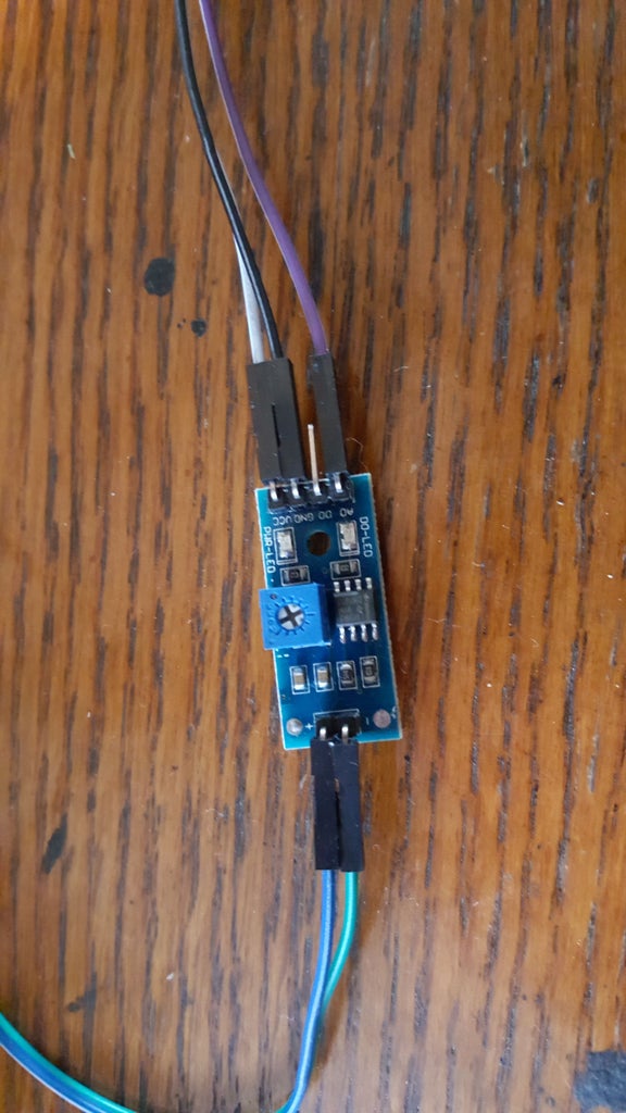
Moisture Sensor Module Setup:
- Pin A0 of the moisture sensor module connects to pin A0 on the ESP8266
- The GND pin on the moisture sensor module connects to a GND pin on the ESP8266
- The VCC pin on the moisture sensor module connects to a 3v3 pin on the ESP8266
(Note: we are NOT using the D0 pin on the moisture sensor. This is a digital "On or Off" output. The sensitivity of the digital output is controlled by the potentiometer on the moisture sensor module. Turning the screw on the potentiometer will change how much moisture is required to turn off/on the output.)
(Note: typically resistors would be used on the RGB leads of the LED. However, the ESP8266 only provides 3.3 volts, so there is little chance of burning out the LED. In this situation resistors are not needed.)
Step 4: Soldering the Circuit


Now that we've tested our circuit with a breadboard and confirmed that everything is working we are ready to put it together on a prototype board. The photos above show the brown colored prototype board I used. I highly recommend using some 16 pin headers as pictured. These little socket strips allow you to plug your ESP8266 onto the circuit. There's several advantages to using these headers. First, if you decide you want to use your ESP8266 for another project, it won't be hardwired to a circuit. You just unplug it from the headers and you're on to your next project. Also, if you mess up the soldering job (oh yes, it happens), you won't destroy the ESP8266 module. If you have never soldered a circuit before, this will be good practice.
Now connect the ESP8266 to the header sockets and position it on the prototype board. I spaced mine to one side and left a blank row of open holes. On the other side I left enough space to easily plug in the RGB LED. Then I cut the board to size using a straight edge and razor knife. At this point I flipped the board over and flatted the pins against the bottom of the board. This helps hold the headers in place for soldering. I then soldered some of the header pins to the board - making sure NOT to solder any of the pins I intended to use.
Now I decided to solder the moisture sensor module to the prototype board, in between the two headers. This way, the moisture module sits nice and tidy underneath the ESP8266. I cut some jumper wire to length and soldered the pins of the moisture module to the appropriate pins of the header using the jumper wire to make the connections. Check the previous breadboard setup step for the wiring diagram (one of the photos).
Now do the same thing with the RGB LED. Poke the leads of the LED through the prototype board and bend them flat against the board to secure them temporarily. Now, where you can, bend the LED leads to meet the appropriate pins on the header. If you cannot make the connection without touching and shorting another connection, use jumper wire. Solder the LED connection points, snip off any excess wire protrusions and viola, you done. You are now ready to plug it in and test it out.
If it doesn't work, chances are something went wrong during the soldering. Either the wrong pins were connected or excess solder bled over to another connection. Either way, you can start over with a fresh prototype board, headers and LED while preserving the more costly ESP8266 board.
If everything works, there's one last thing. This is not required but it will certainly help keep your circuit in solid working condition. I like to hot glue the bottom. This will seal the solder connections and wiring, offering some protection against accidental shorts. I do this by first putting a strip of masking tape sticky side up on my work bench. The same kind of tape used by painters. Then, hot glue the bottom of the circuit generously and squish it onto the tape. After the glue cools, peel it off the tape, cut away any excess glue and you have a nice flat surface that seals and insulates the circuit wiring!

Participated in the
IoT Builders Contest


