

Introduction: ESP8266 Controlling WS2812 Neopixel LEDs Using Arduino IDE - a Tutorial


Hi everybody,
If you're like me, you've been looking around the internet for a good tutorial on using the ESP8266 with neopixel LEDs (AKA the WS2812 or WS2812b), programmed via the Arduino IDE. I haven't found it all in one place, in English, but it turns out it's pretty easy now - much better than a few months ago. First, props to sabas1080 for his instructable, which does a nice job of this in Spanish. I'm documenting it here in English in case this helps others.
This is a basic breadboard demonstration. It's not meant to be a "final product" but consolidates instructions for this basic setup. If you haven't used the ESP8266 yet, it's an awesome little wifi board that you can get for a few bucks. Even the fancy version is only $10.
Note that this DOES NOT require a separate Arduino board, it's running the neopixels directly from the ESP8266 and just programming it with the Arduino IDE. And thanks to the hard work of many people it's now very easy!
Come see...
Step 1: Parts and Assembly


Parts you'll need:
- an ESP8266, I used Adafruit'sHuzzah breakout, http://www.adafruit.com/product/2471
- 3.7v LiPo battery such as https://www.adafruit.com/products/1317
- FTDI programmer such as http://www.adafruit.com/product/284 or USB-to-serial cable
- small switch such as https://www.adafruit.com/products/805
- Neopixels (aka WS2812 LEDs) such as https://www.adafruit.com/products/1463
- Capacitor to protect your neopixels - I have a 1000 uF here.
- ~470 ohm resistor
- Breadboard
- Wire
Note: using the Huzzah breakout board makes things easier because it has buttons built in for reset and bootloader mode. if you're using a bare ESP8266 board, you'll want a couple additional buttons to use for reset and putting the ESP8266 in the bootloader mode (to upload your code to it).
Assembly:
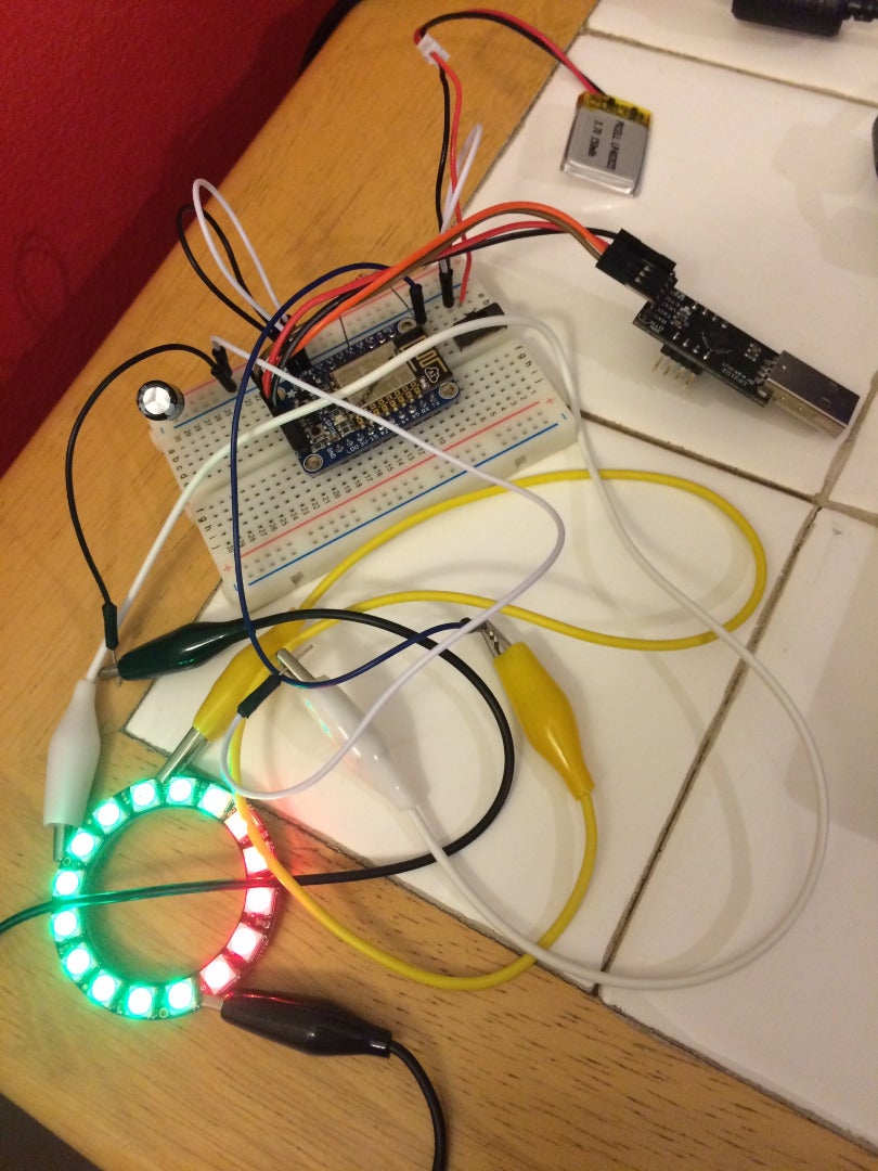
Assemble as shown in the diagram above. The capacitor and resistor help protect your neopixels. I'm using a neopixel ring because that's what I happen to be working on, but you can test with a strip or a single pixel or whatever you have. If you are using the Adafruit Huzzah breakout, solder it as shown on their nice page here: https://learn.adafruit.com/adafruit-huzzah-esp8266-breakout/using-arduino-ide using your breadboard.
You'll need the FTDI cable or USB for programming. After the programming is finished, you can remove it. Speaking of which, let's program this thing.
Step 2: Code and Programming


First, you need to make sure you have a version of the Arduino IDE that is at least 1.6.4. Get it here:
https://www.arduino.cc/en/Main/Software and install it.
Then go to File --> Preferences and at the bottom under "Additional Board Managers", enter:
http://arduino.esp8266.com/versions/2.0.0/package_...
Use the Board Manager to install that ESP8266 (Following Adafruit's Arduino ESP8266 setup instructions here: https://learn.adafruit.com/adafruit-huzzah-esp8266-breakout/using-arduino-ide)
Tools --> Board select generic ESP8266 (Or Adafruit Huzzah ESP8266 if you're using that) and use these settings:
- CPU Frequency: 80 MHz
- Upload speed: 115200
- When you plug in your FTDI, select the correct COM port for it.
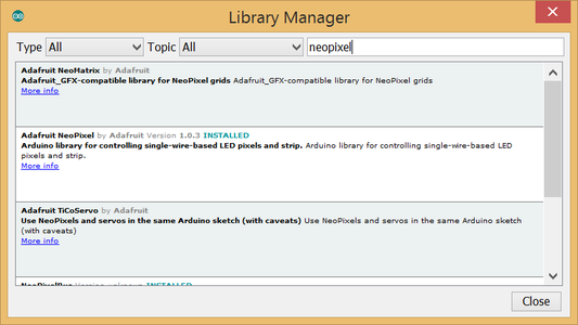
Make sure you also install the neopixel library for Arduino if you haven't already. Get it using the library manager
- In the Arduino Go to Sketch --> Include Library --> Manage Libraries (it's at the top of the list)
- Type "neopixel" in the search box
- select the Adafruit neopixel library and install
Now get your sketch ready. You can use the generic StrandTest sketch in the examples menu under the Adafruit NeoPixel folder. Set the number of pixels you're using and set the data pin - I'm using pin 14.
[NOTE: DON'T USE PIN 16 FOR NEOPIXELS].
Put the board in bootloader mode.
- If you're using the Huzzah breakout, this means holding down the GPIO0 button, pressing and releasing the resent button, then releasing the GIO0 button.
- If you're using a bare ESP8266 instead, then temporarily connect GPIO0 to ground, toggle power to the reset pin,then disconnect GPIO0 from ground.
- If you've done one of the above correctly, the on-board LED should be dimly on.
Now upload the sketch using the Arduino IDE. This will take a while and you will probably see the on-board LED flicker during transfer.
Now that you've uploaded the sketch, let's see if it works. Flip the switch on your battery and you should see your neopixels light up.
Congratulations, you're halfway to making the next big IoT device! Have fun making things light up from afar with your ESP8266.
Hope this saves you time scouring multiple sites to put it all together. Thanks to Adafruit, http://www.esp8266.com/, and http://www.whatimade.today/esp8266-easiest-way-to-program-so-far/ for all the original source material.


