

Introduction: Electronic Instrument


Parts List:
(x1) Arduino Uno (Duemilanove is fine, but make sure it is ATMEL328P) Radioshack #276-128
(x1) Arduino ProtoShield Radioshack #276-140
(x1) PC Board with Copper Radioshack #276-147
(x9) High Tact Switch Radioshack #275-002 (I really liked the feel of these buttons, but they only come in a surface mount version, which makes them fairly difficult to solder because of the small leads. Additionally, since these buttons are square it is harder to drill a hole for them in an enclosure. If you are a beginner, you might want to use a different type of button, any of these momentary switches will work)
(x1) 10KOhm Audio Control Potentiometer with SPST Switch Radioshack #271-215 (this will be used to control volume and turn the device on/off)
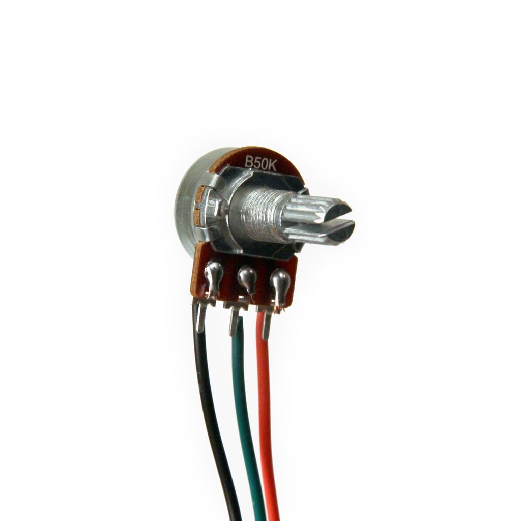
(x1) 50K-Ohm Linear-Taper Potentiometer Radioshack #271-1716
(x2) 220µF 35V 20% Radial-lead Electrolytic Capacitor (or anything between 200 and 300 uF) Radioshack #272-1029
(x2) SPST PC-Mountable Submini Toggle Switch Radioshack #275-645
(x2) Silver Tone Knurled Knob (or any knob with 0.25" inner diameter) Radioshack #274-424
(x9) 1N914/4148-Type Diode (two packages) Radioshack #276-1122
(x3) 2K ohm 1/2W 5% Carbon Film Resistor (1 package)
(x10) 10K Ohm 1/4-Watt Carbon Film Resistor (2 packages) Radioshack #271-1335
(x8) 20K Ohm 1/4-Watt Carbon Film Resistor (2 packages)
(x1) 4.7K Ohm 1/4-Watt Carbon Film Resistor Radioshack #271-1330
(x1) 1K Ohm 1/4-Watt Carbon Film Resistor Radioshack #271-1321
(x1) 5K Ohm 1/4-Watt Carbon Film Resistor
(x1) 9V Alkaline Battery Radioshack #23-853
(x1) Heavy-Duty 9V Snap Connectors Radioshack #270-324
(x1) Amber Super-bright LED Indicator Radioshack #55050630
(x1) White Super-bright LED Indicator Radioshack #55050633
(x1) 1/8" Stereo In-Line Audio Jack Radioshack #274-274
(x1) LM386 Low Voltage Audio Power Amplifier (8-Pin DIP) Radioshack 276-1731
(1x) 8 Pin Socket 276-1995 Radioshack 276-1995
Additional materials:
22 Gauge Wire Radioshack #278-1224
Solder Radioshack #64-013
drill
plywood
polyurethane finish
sand paper
hot glue
super glue
four wood screws
Heat Shrink Wrap Radioshack #278-1610
Electrical Tape Radioshack #64-2375
I've included fritzing breadboard diagrams (divided into a few parts) and schematics for this project as well as all firmware. You can find these documents throughout the body of this instructable or download them all in one zip file below.
Attachments

Step 1: Build Enclosure


I used AutoCAD, Autodesk 123D Make, and CorelDRAW to design my project enclosure. I've attached the AutoCAD, STL, and the EPS files for the enclosure I built below. Then I sent my EPS files to a laser cutter and cut them out of 0.2" plywood. I also cut a front panel out of 3mm acrylic. If you do not have access to a laser cutter, you can buy a project enclosure or find a spare box and drill holes in it for all your components, be creative!
I wanted to sand off the scorched ends of the laser cut pieces so that the outside of the box had a consistent finish, so I also made a set of eps files with some extra length on the ends for sanding ("enclosure long").
I glued the pieces together with wood glue and cut a piece of acrylic for the front panel.
Attachments
Step 2: Wire Buttons


We need to wire the buttons to the Arduino so that we can monitor whether or not they have been pressed. But if we use one input pin for each button we will need to use nine of the arduino's 20 pins. In order to reduce this number down to only six pins, I used a technique called multiplexing.
As shown in figures 11 and 12, multiplexed buttons are wired such that each button shares a common lead with all the buttons in its row, and it shares the other lead with all the buttons in its column. This way we can use the arduino to ground one row of buttons at a time (Arduino D8, D9, D10) and check to see if any of the columns are grounded by measuring the voltage of A0, A1, and A2. Essentially, we will be measuring the states of the buttons row by row. Since the Arduino is very fast, we will not be able to tell a difference in the response time of the buttons when they are multiplexed vs if we had dedicated one input pin to each button.
Multiplexing buttons does bring some complications. Since current can flow in both directions through a button, if two buttons are depressed at the same time, current can flow through the circuit in ways we did not intend and make us think that four buttons are depressed. In order to prevent this, each button is attached to a diode, ensuring current always flows through the buttons in one direction.
Buttons work in the same way as switches, they close an open circuit. Most buttons have two leads (figure 9), but some (like the ones I used) have four leads because each side of the switch is split into two separate leads. By comparing figures 9 and 10, you can see that both types of buttons are essentially the same, but if you use the four lead buttons, be sure to check the specs to locate two leads that are not connected to each other.
Solder a diode to one side of each switch, be sure that the "-" end (usually indicated with a stripe) is facing away from the switch. Solder a (preferably black) wire to the other end of the diode and a (preferably red) wire to the other side of the switch. Do this for all nine switches. You may find it necessary to use hot glue, electrical tape, or heat shrink to reinforce/protect these connections.
Once soldered, mount each button in your project enclosure.
You can find the fritzing files for 2-lead button and 4-lead button multiplexing below.
Step 3: Prepare Arduino Shield
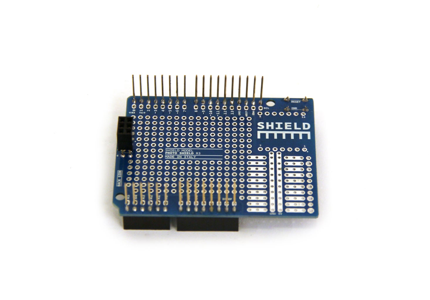
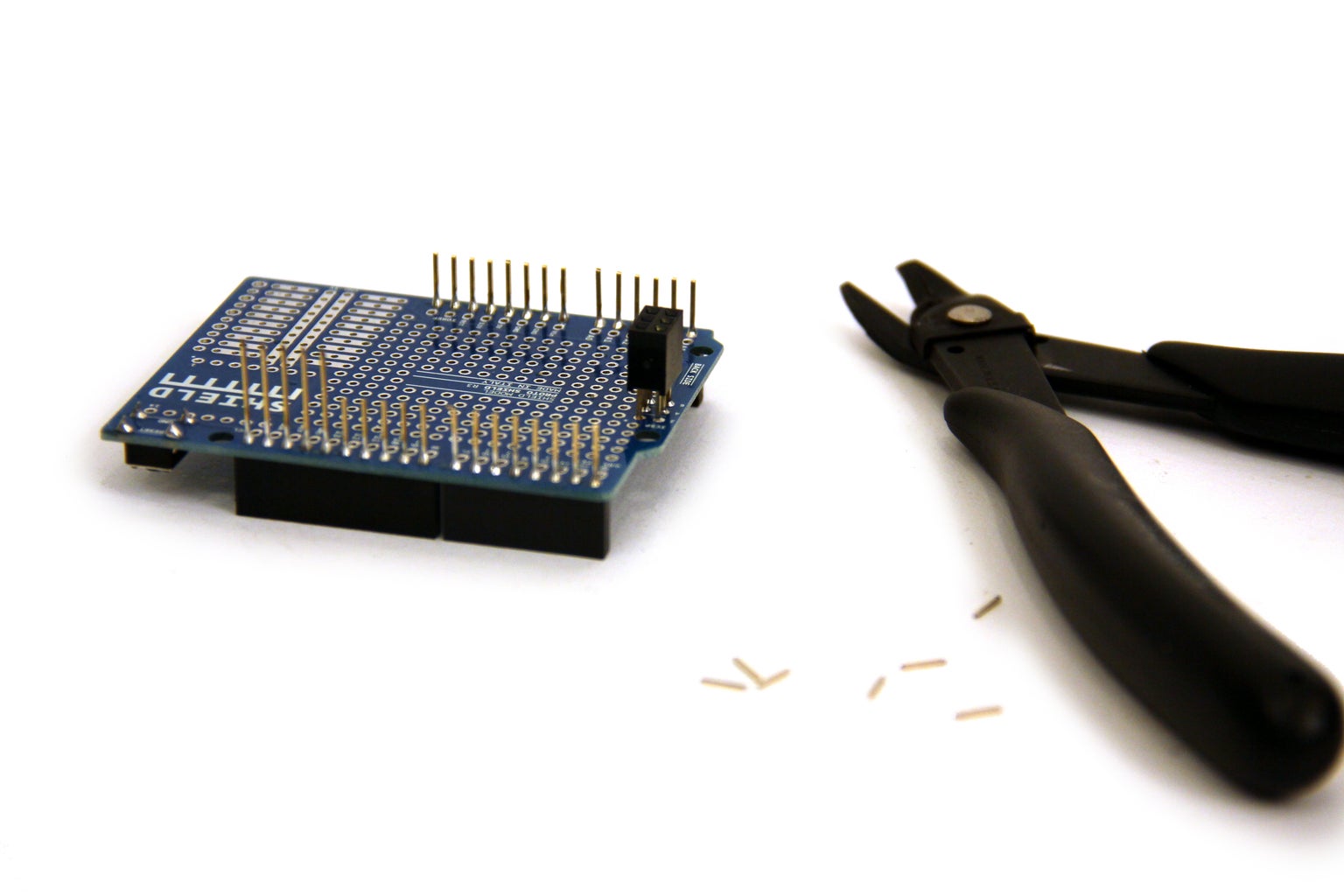
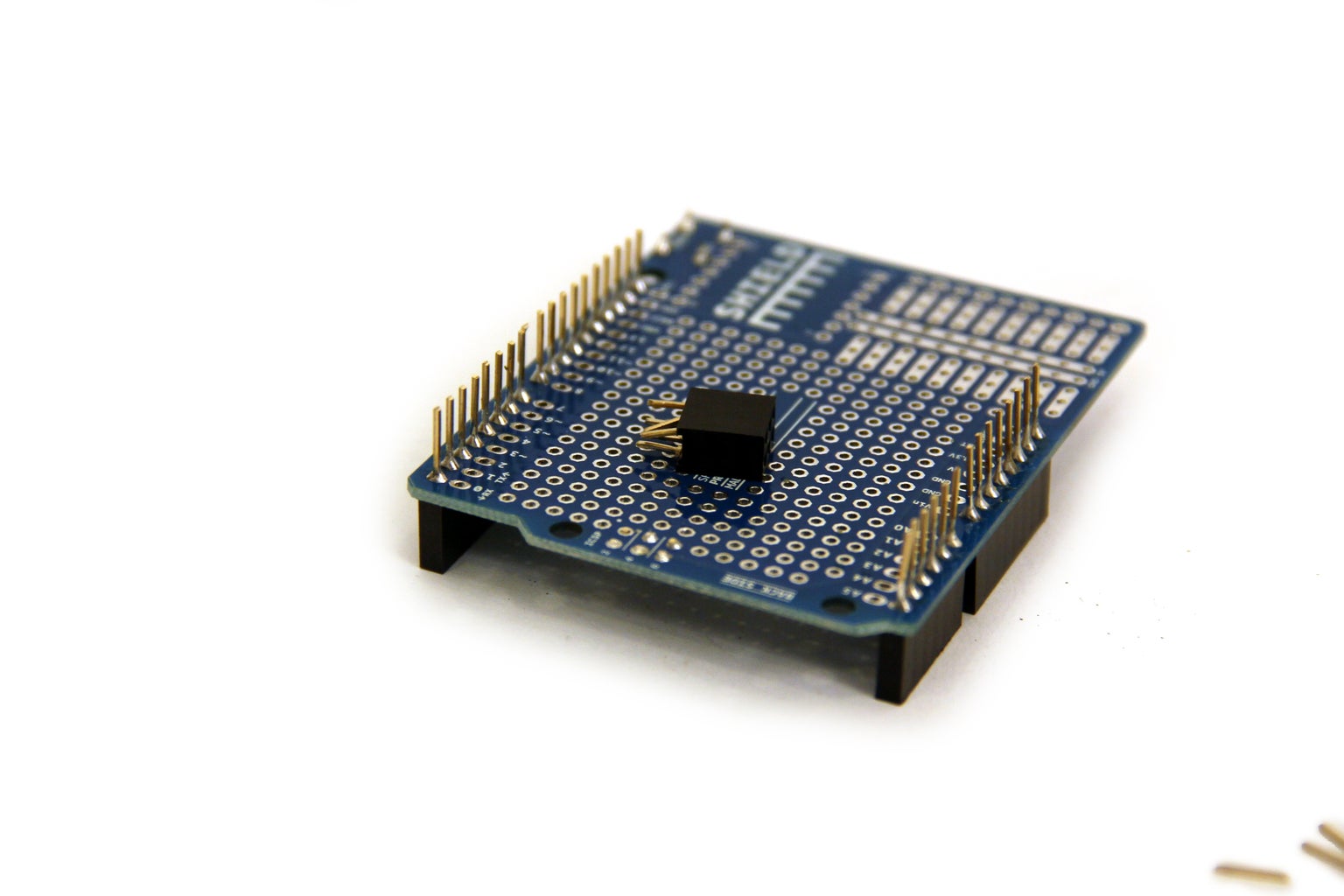


The Arduino proto-shields are a convenient way to attach circuits to an Arduino, but I like to trim them down a little bit first so they do not take up so much room in the project enclosure. Start by trimming the pins down with a pair of wire cutters. Next, cut off the six pin socket. Finally, cut the sockets from the top of the board.
Step 4: Wire Buttons on Arduino Shield - Part 1


Solder three 2kOhm resistors on the proto-shield so that they are five pins from analog pins 0, 1, and 2 (see figure 1) and cut away the excess lead wire. On the underside of the board, solder the resistor leads farthest from analog pins 0, 1, and 2 together and connect them to 5V using a jumper wire. Use three small jumper wires (I used the scrap wire from the resistor leads), connect analog pins 0, 1, and 2 to the three nearest soldering points.
Step 5: Wire Buttons on Arduino Shield - Part 2


Solder the red wires (the lead not connected to the diode) from the buttons to the protoboard. Solder the leads from buttons 0, 3, and 6 in line with analog pin 2, buttons 1, 4, and 7 with analog pin 1, and buttons 2, 5, and 8 with analog pin 2. Clip the excess wire from each of these connections and solder all the adjacent points togther on the underside of the board (see figure 2). Each of the buttons should now be electrically connected to an analog pin and one of the 2k resistors.
Again, I've provided the circuit diagrams and fritzing documents for both 2-lead and 4-lead buttons.
Step 6: Wire Buttons on Arduino Shield - Part 3


Solder the black wires (the lead connected to the diode) from the buttons to the protoboard. Solder the leads from buttons 0, 1, and 2 in line with digital pin 8 buttons 3, 4, and 5 with digital pin 9, and buttons 6, 7, and 8 with digital pin 10. Clip the excess wire from each of these connections and solder all the adjacent points togther on the underside of the proto-shield (see figure 2). Each of the buttons should now be electrically connected to one of the digital pins.
2-lead and 4-lead diagrams and fritzing are provided here, again.
Step 7: Sand Enclosure


This is a good time to sand down the enclosure if necessary.
Step 8: Mount and Wire LEDs


I mounted my indicator LEDs early so I could sand the tops down while finishing the wood in the rest of the enclosure. Sanding down the top of LEDs gives them a frosted surface which makes them nice and diffuse. I used some super glue to fit the LEDs inside two 5mm holes, I left the top parts sticking out so that it could be sanded flush with the enclosure surface.
Attach the shorter leads of both LEDs to each other (grounds) and connect to the ground pin of the arduino protoshield. Attach a current limiting resistor to each of the longer leads of both LEDs. The optimum resistor value can be calculated as follows:
R>=V/I
where:
R is resistance across the resistor measures in ohms
V is forward voltage in volts from LED specs
I is continuous forward current measured in amps from LED specs
For most through hole LEDs the forward voltage will be about 2-3.5V and the current will be 15-25mA. You can check the datasheet of the LEDs you bought to calculate the lowest possible resistor values for your LEDs. I chose to use resistors that were much higher than I needed, beacuse I didn't want the LEDs to be blindingly bright. I ended up using a 1k resistor for the amber LED and a 4.7k resistor for the white LED, these values may be different depending on what type of LEDs you use and how bright you want them, but 1k is a good place to start.
I've attached the fritzing document which includes the LED wiring below.
Step 9: Tempo Pot


Solder three leads onto a 50kOhm linear taper pot. Connect one side to ground (black wire), the other to 5V(red wire) and the middle pin(green wire) to analog pin 5 on the Arduino shield.
Step 10: DAC


DAC stands for "digital to analog converter." We need a DAC because the audio data stored in the Arduino is digital, and we must convert it to an analog waveform before sending it to speakers. A simple way to do this is to use something called an R2R resistor ladder. You can think of it as a multi-leveled voltage divider. It takes incoming digital bits (+5v and ground from Arduino), weights them, and sums them to produce a voltage level between ground and 5 volts.
The resistor ladder for this project is an 8-bit DAC. As you can see in the schematic, Arduino PORT D (digital pins 0-7) output 8 pieces of data (one from each pin) which are sent to each junction of the DAC. I soldered these resistors on a piece of copper plated protoboard I cut down to size.
I added two 0.1uF capacitors to the end of the resistor ladder to act as a low pass filter. This type of filter will remove the higher frequencies caused by the low (8khz) sampling rate of the audio and smooth out the waveform. You may choose to change the values of these capacitors depending on what you like.
There are 10 connections to the DAC, 8 digital input pins from the arduino, ground, and audio out. The green wire in figure 6 is audio out, this wire will connect to the amplifier in the next step. You can find the fritzing file below.
Attachments
Step 11: Amplifier


I cut another piece of protoboard to create the amplifier circuit. Many suggested wiring diagrams of the LM386 can be found on the datasheet; the simplest diagram is reproduced in figure 2. I used a variant of this circuit which does not include the 0.05uf cap and 10ohm resistor. Also, instead of a 10k potentiometer, I sent a fixed voltage to pin 3 of the LM386 using two resistors in a voltage divider configuration. I only had a 220uf capacitor when I was putting my project together, so I used it instead of the 250uf. Additionally, our audio out will be sent to another pot for volume control before being sent to speakers.
Find the fritzing file below.
Attachments
Step 12: Wire Volume(gain) Control Pot


Volume or gain of the audio signal will be controlled with the 10k audio taper pot with switch. Connect the audio out from the amplifier and ground to either side of the potentiometer. The middle is audio out, it will be hooked up directly to the audio jack.
Also connect a wire to the bottom and left leads on the back of the pot (figure 2). This is the switch that will be used to connect to power later.
Step 13: Switches

Solder a 2kOhm resistor and two wires to each switch as shown in figure 1. Connect the red wire to +5V and the rightmost black wire to ground on the arduino proto-shield. The middle wire of the record switch connects to pin A3 and the middle wire of the mute switch connects to pin A4.
Attachments
Step 14: Battery


Solder the red lead from the 9V battery connector to the top left swtich input on the volume control pot as shown in figure 2. Then solder the bottom lead from the switch to a wire and connect that wire to Vin on the arduino shield. This way, when the pot is turned clockwise it will click and connect these two leads.
Step 15: Headphone Jack


Remove the plastic casing from the headphone jack. Solder the audio out from the gain pot (middle lead) to both stereo channels of the headphone jack. Solder ground to the jack. You may want to use some hot glue to reinforce these connections and make sure that they do not short out.
Step 16: Install Components in Enclosure


Place all finished components in enclosure and secure with glue if necessary. I used super glue to secure the headphone jack and switches. Remove side pin from the pots (figures 3 and 4) and secure with nuts on outside of enclosure (figure 5). Connect battery and fit inside enclosure. Cover the exposed circuitry of the DAC and amplifier with electrical tape to prevent short circuits and fit inside enclosure.
Step 17: Screw on Back

If necessary, screw back panel on.
Step 18: Firmware

This instrument can do two different things:
-it can be used as a standalone audio device, with the audio data stored in the arduino's flash memory
-it can also be used to sequence MIDI through a usb connection to your computer
These two functions require two separate pieces of firmware which are described in more detail in the next two steps (download them below). This means if you would like to use it as a MIDI instrument you need to load the MIDI firmware, then if you would like to switch over to audio you should load the audio firmware.
Step 19: Audio Firmware

The audio firmware is the most simple to set up. Download the Arduino sketch provided below and load it onto your board. Once the firmware is loaded, unplug the usb connection and turn off the device (turn the gain pot until it clicks off). Turn the device on, after a moment you should see the white LED turn on. Plug in your headphones and slowly turn up the gain pot while pressing one of the front panel buttons repeatedly until the volume is where you like (be careful not to turn up the volume too high!). I've loaded 9 default sounds in the firmware, try out all the buttons and make sure you can hear all of them.
Once all of your audio is working correctly, flip the record switch, the white LED should turn off and the orange should turn on. Play a short sequence with the buttons and flip the white switch again when you want to start looping the audio you've just played. The white LED should start start blinking on the beat and you should hear your sequence looping.
Flip the mute switch to mute what you've recorded, flip it again to bring it back.
Flip the record switch to record additional audio on top of your recorded sequence, this time you will see the orange LED blinking with the beat.
Attachments
Step 20: MIDI Firmware

To use this device as a usb MIDI instrument you will need to run a serial to MIDI app. I have written one in MaxMSP called "MIDIroute," if you don't have MaxMSP, download MaxMSP Runtime (it is free and located on the right side of the page). In the app, you can select your MIDI out channel and change MIDI note and velocity values (see the comments). When you have the instrument connected to your comp via usb and the app MIDIroute is initialized properly, you should see the grid light up orange as you press a button. If you have just loaded the arduino firmware, you may need to quit Arduino and then briefly disconnect the usb connection to you computer and reconnect to establish a serial connection to MaxMSP.
Read the instructions on the last step to find out how all the controls should work.
Step 21: Editing the Firmware

If you would like to make changes to the firmware, please read the comments I have provided. The more important comments are written in the following format:
/*********************************************
IMPORTANT COMMENTS
*********************************************/
these comments will let you know how to make some simple changes such as:
-where to insert new stored audio data
-how to change the resolution of the sequencer (16 step, 32 step...)
Step 22: Prepare Audio Files


Customize your instrument by loading your own audio files onto it! Since all audio is stored on the memory of the Arduino, you'll need to compress it heavily to get it to fit. This device uses 8 KHz, 8-bit mono audio that has been converted into an array of bytes. You're only going to be able to store about 4 seconds of audio total, so keep the nine samples very short!
Down sample the audio in iTunes:
-import your sample into iTunes
-open Preferences and select "Import Settings" (figure 1)
-select import using mp3 encoder and custom settings (figure 2), this will open another dialog box (figure 3)
-copy the settings from figure 3 - “Stereo Bit Rate” of 16 KHz, a “Sample Rate” of 8 KHz, and Mono “Channels”
-right click on the files you want to convert and select "create mp3 version", listen to it to get an idea of what it will sound like, 8kHz is very compressed, so high frequencies will be attenuated
-remember to change your iTunes settings back after you are done.
Convert to byte array:
-Download the Encode Audio Processing sketch below for mac, windows, or linux. This program was provided by the people at high low tech.
-open Encode Audio
-you will be prompted to select the file you wish to encode
-a dialog box will appear letting you know that the data has been saved to your clipboard
Insert in Arduino Firmware:
-paste the data into one of the sample# storage spaces (figure 4), it should be in the following form:
byte sample#[] PROGMEM = {PASTE HERE};
The position of the samples on the grid is given in figure 5.
Enjoy!

Participated in the
Make It Real Challenge

Participated in the
Woodworking Challenge


