

Introduction: Electronic Ultrasonic Emitter - Basic Version


Hey up there! Here's my new basic project for all ages! I am here again with another Arduino Nano project. Today we are going to create a device that emits ultrasonic waves in the air that could be possibly repelled mosquitoes, cockroaches, rats or even create a dog whistle. This is a multi-purpose project with Arduino Nano! Come on, go ahead and read some information below.
The Electronic Ultrasonic Emitter - Basic Version
This is also known as The Project E.U.E or Electronic Ultrasonic Emitter with a version of basic. This is a traditional stuff device that could possibly repel mosquitoes, cockroaches, rats or even use as a dog whistle. The Project E.U.E consists of 4 electronic components including the 2 pin jumper and the black wire. The project is controlled by a microcontroller which is the Arduino Nano Atmega 328P. It has one speaker (piezo passive buzzer) that emits frequency from 20Khz to 170KHz (the real problem here is that the Nano has only 65535 maximum frequency so that this project emits frequency from 20KHz to 65KHz in reality). These ranges are safe and not annoying because it is completely no noise from this device. It has a light indicator (besides the LED indicator on the Arduino Nano) which is the RGB Module. The RGB module is optional it's up to you if you want to have an indicator to your device because, for me, it is a lot easier to recognize my working device at night when it's dark. I made it blinky to feel like I am watching blinky Fireflies at night lol.
Features
- Uses frequencies above the audible range of normal human hearing, about 20-170 KHz.
- Portable. (You can bring this stuff on your camping trip or in travel.)
- Powered by Portable Charger.
- Being Awesome!
The Purpose of the Project (For Me)
The purpose of this project for me is to repel mosquitoes in my room. Mosquitoes are my problem at night, they bite me each night and that's not good for me because I was experienced 4 dengue cases for the past years. I don't want to have a dengue again. So, I decided to make this device to test if the frequencies from 20KHz to 170Khz (correction only: 20KHz to 65KHz in reality, Arduino has limits) will work.
The Research (My Own Research)
Night One - After I made this stuff, I have tried! I run this project 3 days without powering it off. What I mean is 24/7 running this device. The first night, approximately 50% of mosquitoes are gone. How I prove that 50% is gone? I based it on my mosquito bites. Every morning I have 5-10 or 7-9 bite marks on my skin (mostly on my feet). When I wake up on the second day, I noticed that I have only 4 bites only which is half of 5-10 bites.
Night Two - For the second night, I have placed it in the center part of my room, so that it will widely emit ultrasounds across the room. The result for the second night, I have only 2 bites on my feet which are approximately 80% of mosquitoes are gone and left me lol.
Night Three - The third night was very awesome! I placed it in the same place as night two. The result is very unbelievable because I have no bite marks on my skin which is 100% of mosquitoes are gone in my room. I still continuous running this device until now to keep my room mosquito-free.
NOTE: This is only my own research and does not guarantee that this is valid proof that my project is completely effective. I consider always the effectiveness based on the users of this project. You may contribute and give it a try.
The Science Behind
To be cleared, I use the 40KHz or frequency which is higher than 20KHz and 30KHz. I have used 20KHz first for one week and I found it ineffective. The 30KHz is also ineffective and still, I have bite marks from running it for 1 week. So I spend 2 weeks for testing those frequencies. I decided to use higher frequency such as 40KHz and I found it effective (For me but I don't have an idea if this device will work for your - give it a try instead). The 20KHz to 170KHz are said to be the Dragonflies' wing's sound frequency, which is the predator of mosquitoes. I, therefore, conclude that mosquitoes are repelled by the sound from my speaker because they thought that my room is a dangerous room to live hahaha lol. They said, the ultrasonic repeller is pseudoscience and not effective at all. I do believe it but still, I give it a try by making this project. In the end, it works for me and it helps me a lot to fight those mosquitoes.
Want to Contribute?
I need you (I am not gay if you are a male LOL), but seriously I need your help to test this project if it is really working. Anyone can help me to provide proof of the result of this research. If you have a unique way to test it please comment it below or if you have a video testing it, please also include the link below the comment. Sorry but, I am in the middle of the ineffective and effective scale of this project. For me, it works but for others? I want to know and I am very curious about what would be the result of the research thanks, guys! Hopefully, understand and fulfill curiosity.
Disclaimer
This project is for fun only and not 100% works for any situation at any time. There is no proper experimentation that proves that this device is tested and can repel mosquitoes, cockroaches, and rats. The author is not liable for any direct or indirect damages from making this project. This is for fun and educational purposes only. The author is encouraging the viewers to give it a try if you have recent research about the project please comment it below.
Caution
"Do not use the range from 2 MHz and up because this is the dangerous frequencies that are used for medical purposes. Might affect your health please read some information below link about effects of ultrasound to human."
Link: http://www.wikilectures.eu/index.php/Effects_of_Ultrasound
Hopefully, you have read all the things you should know about this project. This is my second instructable, why not to check my first instructable below and give it a visit and check out!
The project is sponsored by my two partners electronic shop, the Hive Electronics (the DIY KIT provider) and ConnectedCities (another option to buy the parts from this instructable). Are you willing to give it a try? Excited to make this stuff? Well, what are you waiting for? Go and head to the first step!
Step 1: What You'll Need!


The project requires few electronic components. The parts you'll need are available in your Arduino Starter Kit. If you don't have a starter kit or don't want to use it. You can purchase the parts in a ready DIY KIT provided by Hive Electronics. I recommended purchasing the DIY KIT because it is discounted instead of purchasing the parts individually which can be expensive than the ready one.
Grab your copy of DIY KIT here: Hive Electronics(Free PDF Documentation and Stickers)
You have an option to purchase the DIY KIT or buy the parts individually. I have a suggested electronic store to purchase some of the electronic components for this project and it is the ConnectedCities. Here's the list of the electronic components you'll need to this project!
- 1 x Arduino Nano Atmega 328P (with USB Cable)
- 1 x Piezo Passive Buzzer
- 1 x 170-Point Breadboard
- 1 x RGB LED Module (optional)
- 1 x Black Jumper Wire
- 1 x 2 Pin Jumper
- 2 x Male Pin
- 1 x Portable Charger (4400mAh)
- 1 x USB Detector (optional for testing)
The Arduino Nano can be bought to ConnectedCities and the rest can be bought on the electronic stores near you! The electronic components are very basic and can be found in any electronic stores out there. The project has no tools needed to do. You just simply plug all the components on the breadboard and ready to go! It's up to you if you want to make it permanent. If you want to make it permanent please use the perma-protoboard of Adafruit and don;t forget to share with me your version. Now, if you have your parts then go to your workbench and let's make something amazing today! Check out the next step.
Step 2: Plug the Brain


Get your Arduino Nano and your 170-point Breadboard, then gently plug the Arduino Nano to the Breadboard. Check the images above for more guide. Also, check the last image for the exact location of Arduino Nano to the Breadboard. After placing the Arduino Nano to the Breadboard please jump to the next step!
Step 3: USB Detection Fixer


What you'll need in this step is to plug the Pin Jumper I made. To make this stuff, get the 2 Pin Jumper and the 2 Male Pin look at the first picture above. Then connect them as you can see on the second picture, look closely and carefully follow the images above. After connecting 2 Pin Jumper and 2 Male Pin, now you have a Pin Jumper!
Plug the Pin Jumper to A6 and A7 of Arduino Nano look at picture 3 and 4 for clear guide. Also, check the last picture for details. Why did I this? As I learn from creating my last project. By shorting the pins 25 and 26 you are able to fix the USB detection issue on Arduino Nano which will prevent you from uploading codes to the Nano. By doing this you are able to upload any sketches to the Arduino.
After that, jump to the next step!
Step 4: Add the Blinky Indicator


In this step, get your RGB Led Module and plug it according to the images above on how I place it on the Breadboard. Look at the last picture for a more detailed guide. The RGB LED Module is an optional electronic component of this project. The reason why I put an RGB LED Module in this project, is it because I want an attention seeker blinky lights when it's dark. It's up to you! If you want a blinky indicator in your E.U.E. Another reason is I want blinky lights like fireflies at night while I am listening to Owl City's Fireflies song. Anyway, let's get back to the project, after plugging the indicator jump to the next step!
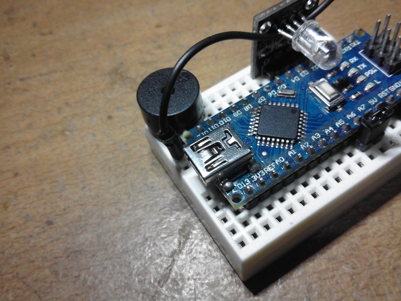
Step 5: Plug the Sound


Now, we are going to add sound frequency source! Go ahead and get your guitar and amplifier and let make some noise lol! But seriously we are going to add the source of sound in our project. By doing this, get your passive piezo buzzer and plug it on the Breadboard and slap the person on your right side lol that's a joke, just plug it hehe. Check the pictures above for more info and details. Jump to the next step after this step.
Step 6: Add the Ground


The last step in placing components to the project. Get one black jumper wire and plug it according to the pictures above. Why I use black jumper wire? Traditionally, black wire in electronics is considered as ground wire or negative wire. Please double check the pictures above, the fourth picture shows that I place the middle part of the jumper wire in the RGB LED Module's LED to make it more presentable look. It's up to you how you make your project presentable. Also. check the last picture for a detailed guide.
Step 7: Feed It Up With Codes


This time we are going to upload the sketch I made for this project. Please check the images above and check the settings I have from my Arduino IDE. The code can be downloaded below. If you want to contribute please visit this GIST on Github.
DOWNLOAD THE CODE (Package .zip)
COPY & PASTE THE CODE (Copy, Paste, and Upload)
Step 8: Power It Up!


It's almost done! Let's make our project alive! How? Let's powering it up with a portable charger. I have a portable charger which has 4400 mAh. This is good enough to provide power supply in a long run. The Arduino Nano has 20 mA when running. Let's say the LED's on RGB has ~20mA each. Then the Piezo Active Buzzer has ~5 mA current. We will sum their current rating to get the average mA of the whole circuit.
So we have;
~20 mA + (~20 mA * 3) + ~5 mA = ~85mA.
We have a total of ~85 mA power rating. If we have 85mAh for our project, this will be good only for one hour of operating time. 4400mAh power supply from my portable charger should be good for 52 hours of operating time. This is equivalent to 2.2 days operating time. Not bad for being a repellant for mosquitoes.
Here's my calculation;
4400mAh / 85mA = 52 hours of operating time.
52 hours / 24 hours = 2.2 days
Again this is not bad, besides of being awesome of the project it also portable. You can decide what power supply you want for your version of this project. If you don't want to use the USB cable as the power supply. You can use the Vin Pin on the board which is the Pin 30.
Have you decided what power supply you should use? Well, if yes, are almost done! Go to the last step and check out some information and tips about this project. Thanks for being awesome and joining my journey on microcontrollers.
If I have errors in my calculation please let me know, so I can correct it as soon as possible. My calculation might be wrong because I am not licensed, engineer. I'm just a geek and an Arduino enthusiast.
Step 9: Enjoy!


Hey there! Thanks for taking your time to read and view my simple and basic project. A lot of fun doing this stuff. I hope you enjoy making it as I enjoy documenting this simple Arduino Nano based project. I have a few finish product of the project. The first three pictures are the latest camera shot. The next two pictures are old one when I start, my own research. The last three pictures are the initial build of the project without Breadboard. I found more convenient and easy to store the project If I use a Breadboard. So yeah, I'm right! The project looks to become more awesome. Awesomeness overload lol.
Tips
- Place the project in the center of your room same level of your bed.
- Use a wall USB power supply for a long time operating hours.
- If the room is too quiet, get your headphones and listen to your favorite song to avoid the effect on your ear.
- Keep it away from children.
I am very happy to share this simple project with you, please follow me for more awesome basic and advanced project. You can also check my recent project here. Hit the love button above if you really find this project awesome. Also, share the project in your community or in your social media accounts. By sharing this project means a lot to me. Your support is my inspiration to continue making high-quality contents on Instructables.Don't ever forget to vote this project on Microcontroller Contest.
This project is made possible by:
- Hive Electronics (DIY KIT Provider)
- ConnectedCities (Sponsored Store)
Yeah! If you have some questions, suggestions, or even correction to my Instructable. Please comment it below and I will respond to you as soon as I can. Please be constructive and be nice while posting your comment. I will listen to any opinion and thought you may have. Thanks, guys! Until next time to my next project!!!
Coming Soon: Electronic Ultrasonic Emitter - Pro Version

Participated in the
Microcontroller Contest 2017


