

Introduction: Electronic Lock With One-wire IButton


In this instructable I will present a small little circuit which can replace an electronic lock, electric appliance switch, or anything similar, to a better, cooler one. This little board can assure you, no one will ever enter your room, house, lab, or open a box you don't want to be opened. Another way to do this would be to add some buttons and some electronics to ask for a key combination, however that is asking for a display, and is leading to complexity.
I've had some iButtons and iButton sockets for quite a while, finally I've decided to put them at use, if not else, in the shape of an instructable. Finding small processors, PIC-s, AVR-s in my lab isn't that hard, I picked one with low pin count, a PIC12F683. These little fellows have analog digital converter, comparators, pwm modules in them, they're a good start point for anyone who's trying to get into the PIC business. Given their smaller amount of features - at least compared to their other brothers - they don't have too many peripherals multiplexed on a certain pin. That being said, there won't be any problems with peripheral interference with a minimum configuration.
In the beginning, when I was working with these smaller PIC-s, I only had to look at my code for a few minutes to realize, what is overriding my output signal on pin 5, for example. It was the comparator, which should be turned off, whenever you're not using it, it has primary control on the pin, where the comparator output is multiplexed.
When using larger processors, there are plenty of modules to look at, not just two, as it was in this case (the other was the CCP module).
What you're going to need:
- iButton
- iButton socket
- a PC with MPLAB IDE and HI-TECH compiler on it
- PIC programmer
- PIC12F683
- soldering iron and equipment
- LED-s, resistors, capacitors, transistors, pin headers or screw terminals, button, buzzer
- PCB or perfboard
What I've had extra:
- logic analyzer
Well, let's see what we can do to make such a device!
Step 1: Interfacing Components to a PIC


On the hardware side, things are pretty simple, I'm going to explain how to connect each component to the PIC, by referring to a single schematic drawing.
Connecting LED-s
To make something light up should be the first thing to do, when using a processor. If it lights up when you want, and goes out when you want, it means, you have your processor running your algorithm.
If you have a multimeter around, you can easily test the LED pins, just turn the multimeter switch to diode testing position, and make the LED light up with the probes. If you have the plugs the way you should, when the LED lights up, you'll have the cathode on the black wire, and the anode on the red.
Connect the anode to a PIC pin, and the cathode - through a resistor - to the ground. The resistor value is easy to calculate:
R = ( Vcc - Vf ) / If
We have Vcc at five volts, our LED forward voltage at about 2 volts, and we need a current of ~10-20 milliamps.
That gives us a value of 300 ohms.
Connecting buttons
When there isn't any constraint stopping me, I usually use pull-up resistors to interface buttons to a PIC. A pull-up assures you, that there is always Vcc on the pin, when the switch is not activated. When you press the button, you'll bring the pin voltage down to 0 volts, that will be read by your program, effectively detecting a 'key pressed' event.
You can also add a capacitor in parallel with the button, for debouncing.
Connecting a buzzer
I got this from a broken alarm clock, beeps twice when has voltage across its pins, does nothing when it doesn't. I connected it straight to a general purpose IO.
iButton socket
Since there isn't anything in the spec about the way you should connect this, just take your multimeter, and test out which is the outer ring, that goes to ground, the other will go to another general purpose IO.
Connecting transistors
You'll have to limit the current flowing to the base of the transistor, so a resistor will be needed. The value depends on the type of transistor you're using. I used a BC548B bipolar transistor.
From its datasheet we know, that its current gain is about 200. I will use to drive an approximately 500 mA load. The base current needs to be at least 500/200 = 2.5 mA. That means we need a resistor of ( 5 - 0.7 ) / 2.5 = 1720 ohms. A close value is 1.8k.
That's kind-of the list of components I put near the PIC in this project. Let's build it!
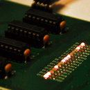
Step 2: Building the Circuit
There are two way you can go by, when doing this: you can either make a PCB, or just use a perfboard to wire everything together.
This is not a complex schematic, but I encourage eveyone to make a PCB for it. It's just easier to deal with later on, not to mention the fact that a custom PCB always looks nice. Especially when compared to a spaghetti-perfboard, right? :)
I made a PCB for this project, following the schematic you can see on the image.
What is on there:
- PIC12F683 doing the processing
- Blue LED signalinc power on
- green LED - lights up when key fob is accepted
- red LED - lights up when key fob is rejected
- buzzer - beeps twice if key is accepted, beeps 10 times if it's not
- transistor - connects to an external load, a relay in my case
- button - saves the serial number of the currently attached key to the internal eeprom memory
- iButton socket
- terminals, wires, filter caps
When putting everything on, start with the component with the lowest profile, so you don't have to straighten component legs later on!
I forgot to add a 5 pin header for programming, so I soldered a 5 wire ribbon cable to the bottom side of the board, and connected through that to the pickit. A word about the pickit: It can be bought, or built, this one is a home made clone, it's working perfectly, and hadn't ever made me cry for an original one. Again, I encourage everyone to build this for himself.
Now, let's move on to the boring part: reading the specs of the 1 wire protocol.
Step 3: How One Wire Works


The DS1990A datasheet contains everything you have to know about the timings that need to be respected when reading or writing it.
The images show you the timings and the levels you must respect to be able to communicate. Setting a pin to an input is done by setting the coresponding TRIS bit to '1', turning it into output means a '0' at that bit position.
Putting out a '0' on the pin is done by simply saying GPx = 0; where x is the GPIO pin number you connected your socket to.
In order to make this instructable as complete as it can be, I will give you the full code (even though I don't really like the idea of not giving in all to make stuff work). I'm not sensitive about anyone using this code to complete his or her projects, you mentioning (or not) where the code came from is for you to decide.
The code itself is self explanatory, the timings were made with timer 1, in polling mode. I didn't wanted to overcomplicate the project with interrupt service routines. I just clear the flag, set up the timer to give me the correct timing, and wait until the flag gets set again. This happens when TMR1 regsiter turns from 65535 to 0.
The smaller the value in it, the longer it will take for the flag to set. That's all there is to it!
Shorter timings don't really worth to be done this way, I used inline asm commands to do that. A single nop operation takes exactly one instruction cycle to complete, which - in our case - is 1 microsecond.
The macros were used to keep the code clean.
Step 4: Testing the IButton Project


I got to say, the analyzer was a real help with debugging the project. I made a screenshot of what I get back from the little device, when I send it the ROM dump command: 0x33.
The analyzer even has a one-wire decoder, so you can actually see the bytes. The six bytes from the middle are shown on the iButton itself, too. I also wrote a routine to write the stuff the firmware reads from the fob into the EEPROM of the PIC12F683.
Then I made a read of the device with my pickit, you can see the result on the second image: the first six bits are the numbers from the key fob, signaling that my algorithm is working fine, and the eeprom was successfully written.
A possible development could be to store the recorded id-s in the eeprom, read it every time the program starts (though that would need a lot of RAM) and constantly compare them against the id-s that ar coming from the connected iButtons. This way one could simply create a list with the iButtons allowed to open the lock, and reject anything that isn't on that list.
Step 5: Dealing With Bad Conscience

So everything is done now,, key fobs are recorded, and stored in the eeprom. I wrote a small memory management program which safeguards the data already stored in the internal EEPROM. When a new key is connected, it is rejected until the button is pressed. When the button is pressed, the program starts looking for an empty 8 byte array in the EEPROM. Once it finds 8 consecutive FF-s, it proceeds with saving the data to that location.
You can see three arrays of key fob ROM data on the image here, This PIC read was made after I registered the three key fobs shown in the video. Again, these are the exact numbers you can see on the fob itself, some sort of a serial code.
I even made a small movie clip for you to see how it's working, and what do you need to do to register your keys.
I also uploaded the full code with the MPLAB workspace for even easier configuration. This means, you only have to make sure to have HI-TECH installed in the right place. Of course, if this version of software is fine for your task, you can write the hex to your PIC, and you're done!

Step 6: Final Words, Cleaning the Table
Finally, I want to wish everyone happy after-building, and if there are any questions, feel free to ask.
Thanks for reading through my second instructable!

Participated in the
Microcontroller Contest


