

Introduction: End of World Initiator


Four switches when thrown in the correct sequence cause a buzzer to sound. The resulting incessant irritating noise causes people to wish the world comes to an end. And what people wish for, they get.
Sometimes.
Step 1: The Circuit

This was inspired by a scene in an animated cartoon about a "crazy frog". Our hero goes underwater and does things which irritate somebody and he throws a series of switches, pulls a lever and, with an impressive sweeping movement, pushes an illuminated red button. A huge, lumbering monster of a robot comes to life and starts smashing things, but our hero - dig the spigot under his belly - escapes unscathed.
I wanted one. A huge lumbering monster of a robot which will come to life when a red illuminated button is pressed and start smashing everything in sight.
So I decided to build one. The button to control the robot, I mean. Since there was no robot to control it will have to control something profoundly significant and what better use than to use it to initiate the end of the world?
OK. For now, it only makes a noise, but I guess you will get the general idea.
It is very difficult to design a circuit like this. Almost impossible. Doctor Johnson was forced one evening to endure a piano recital by the hostess. This was before dinner and he was hungry, so he could not just walk out. At the end of it he was rudely awakened by the polite applause of those guests who had remained awake.
"You know, Doctor," the hostess gently rebuked him, "that was a most difficult piece."
"Difficult, Madam?" was his reply. "I wish it had been IMPOSSIBLE."
Now this is that sort of impossibility. But it was made possible by the advanced circuit simulation and design software, (SP)ICE 7.3.01 Release IV (gamma) which instantly freezes every computer on the network and blows the main fuse, so that further work has to be done on paper by candlelight. Which explains the general scarcity of components in the circuit.
Switch S1 controls the power to the circuit. In the 'off' position any charge on capacitors C1 and C2 are removed via diodes D1 and D2.
When S1 is switched on, if S2 is in the resting position (shown) C1 charges to the supply voltage of 5 volts. When S2 is operated, if S3 is in the resting position (also as shown) its charge is redistributed with C2, and since their capacitances are equal they both get charged to half that voltage, around 2.5 volts. Then if S3 is changed over, one contact of the pushbutton gets this voltage. Now pushing this button will apply a current to the gate of the SCR via R1 and it turns on. R2 prevents it from turning on due to transient pickup on the gate lead. Even after the gate drive is removed due to capacitor C2 running out of charge the SCR will remain 'on' and it will only turn off when switch S1 is turned off.
I did (could) not design a PCB for this circuit because for one, the computers had all frozen, and second, any potential collaborator I approached was scared stiff. This world was dear to them, and they did not want anything to do with the process of initiating the end of it. Even remotely.
So I had to go it solo. I am very proud of the achievement, prouder than the injun who has just outwitted a couple of cowboys.
Step 2: Gather Components

The photo shows the components I gathered to construct the prototype. You need four switches. They can all be of the same type, SPDT toggle. I have here two toggle switches, one slide switch, and a pushbutton. Since these directly affect the look of the finished project, it is advisable to use the largest, klunkiest switches you can find. It has to look BIG and COMPLEX. Throw in a few ICs, transistors, and other junk and pretend that they all have a say in the working of this gadget.
Pick something nice and loud for the buzzer. And make sure it will work at 5V. The one pictured works at 3 volts, and so I could use two AA cells to check it out.
That little thing looking like a transistor is the SCR. You can use whatever you have available, though with larger devices it might not stay latched 'on' with the current through the buzzer.
Similiarly, any diodes will work. The two resistors are 1K and 10K, brown-black-red and brown-black-orange. Those red and orange can be hard to distinguish. It would be best to measure them using a multimeter before installing in circuit.
Those two capacitors can be anything in the range of 1 microfarad to 100 microfarads, nothing critical. They must be approximately equal. Aluminium electrolytics are ideal. If you try tantalum capacitors, be warned that they may die suddenly in this sort of circuit.
If you are reusing them, make sure that they are not leaky. Speaking of leaks, that spigot under his tummy must be for taking a leak. Under water, that would not show, and might be that is why those people had gotten pissed off and were chasing him. I'm talking about that crazy frog animation. Leaks, if present, will seriously degrade the operation of this circuit. And nappies would not help.
Step 3: Rats Nest Construction

I shall construct my prototype in the open, without supporting insulating material. This is called, variously, as 'birds nest' or by some other names. Since I do not like to apologise to any bird I shall call it something else.
To solder two solid wires together, form hooks at both free ends, interlock them and squeeze to make a secure mechanical joint. Then apply just sufficient solder to wet it (shake away the excess) and you get a neat and reliable joint. The idea is to avoid moving the joint while the solder solidifies.
Make sure that it is the 10K that is soldered across the gate and cathode of the SCR. If those two resistors are reversed, the circuit will not work - or at least not until the supply voltage be raised above 12 Volts.
Highlight the connections you have made, and test your work. The stress of soldering can cause some components to give up the ghost, and the sooner you discover that, the better.
Step 4: Test Buzzer and SCR

After soldering in the components highlighted in the circuit diagram, it is time for a quick check. I used 3 volts from a couple of AA cells for this test. A red LED with a 330 ohm (orange, orange, brown) resistor was connected across the buzzer. The buzzer itself came from some equipment and had a plug at the end of its leads. A mating connector was pulled off a circuit board and connected up with a piece cut from ribbon cable.
The additional LED and resistor have not been drawn in on the circuit diagram.
Troubleshooting: No, I do not mean what to do if the world goes on. I mean what to do if that buzzer does not sound.
Connecting A to K (bypassing the SCR) should make the buzzer sound. If it does not, try connecting the buzzer directly to the battery, and try reversing it. Change battery, polarity, and buzzer until your circuit passes this test.
So now you know your battery and buzzer are OK.
Connect the free end of the 1K resistor to the battery positive (use a length of wire). The buzzer should sound, and keep on doing it until you disconnect the battery, and remain silent when you reconnect the battery.
If this checks out okay, your scr is working. If you can't get an scr or, if you are satisfied with a momentary 'pip' you can substitute an ordinary transistor for the scr.
SCR is short for 'Silicon Controlled Rectifier'.
Step 5: Fit the Switches

I have fitted the switches at the end of flexible wires. This is to allow them to be fitted in suitable places on an appropriately adorned box. Using differently coloured wires will help in troubleshooting but using the same gray wires from computer ribbon cable helps confuse anybody trying to trace the circuit.
I have highlighted the completed connections and the next step should be obvious from the diagram - fit the capacitors, pronto.
Step 6: Test Again

After the two capacitors have been connected up, it is possible to test for proper opertion, still with the 3V supply.
Operating S2, S3 and pressing the button should cause the buzzer to sound. Restart the operation by removing one battery wire and touching it to the other. This simulates the operation of switch S1.
When this check passes you are almost there, all that remains is to fit that switch S1 and the USB cable.
I had a dysfunctional USB memory stick and its connector ('A' plug) was extracted. A USB extender cable was plugged to it to make it reach the port on the computer.
Alternatives are a 'B' socket and USB cable, or, to get a cable and cut at the 'B' end. Or use a battery inside the box. But a USB cable looks cool, and if you use a large enough box and patter about spiegel and Dee floppys and Jay Kar flippies and transition diagrams and how hard you hammered at your computer to design it - yeah, you can fake it to the unenlightened.
Step 7: The Completed Device, and How It Works.

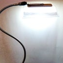
The photo shows my completed prototype. It shall soon be placed inside a box somewhat like the first picture.
How does it work?
Constructing any electronic device consumes energy. To be more specific, high grade energy is converted into low grade, thermal energy. This process irreversably increases the entropy of the universe.
When the entropy of the universe reaches the maximum all the energy in the world will be in the form of thermal energy. Then the world as we know it will come to an end.
Thus constructing this device and operating it will cause the eventual end of the world. Since initiating the end of the world is such a serious affair, not to be entered into whimsically, those three switches have to be flipped in the correct order, the transparent cover on S4 swung aside, and it pressed, all the while concentrating your mind on the correct sequence of events.
What if, after you build it and turn it on, the world does not come to an end?
It will, laddie. Just wait long enough.
Step 8: List of Parts. Acknowledgments.

See figure for a list of parts. It is a fairly complete and comprehensive list, one lawyers will like, because the last item says "anything not covered by the rest of the bla bla" and that is how lawyers talk.
Speaking of lawyers, I just remembered that some lawyer with a need to justify the hefty bleed he is putting on that company might take it into his head to write to me on the 'anguish your actions have caused my client by posting a picture of their mutilated stationery' yeah right. I had written a parts list on that part and it turned out to be wrong so I tore it off. The amended list, on the unmutilated paper is below and I wish to place on record my gratitude to Freescale for sending this pad of post-it notes (among other things) to me. Just shoot that lawyer, if you have any.
I have marked the voltages to expect at various points in the circuit. Nothing very surprising there, either the supply voltage or half that.
This circuit is very economic in current consumption because the maximum current at rest is the leakage of the SCR, the two diodes and capacitor C1. If you select one with low leakage for that position, the battery can be made to last a long time. So leakage, of any kind, should not be a reason not to build this circuit.
Have Fun.


