

Introduction: Energy-Saving Light


In the spirit of Earth Day, I have created a revolutionary new energy-saving lighting solution that is only ever on when your eyes are open. This is remarkably more efficient than normal lighting that remains on, even when your eyes are shut. Using my device, you get light when you need it, and darkness when you don't. This is not only beneficial to you and your energy bill, but great for mother Earth.
This device was made as part of my ongoing effort to use less energy, reduce my footprint, and prevent climate change. I foresee similar technologies being implemented in televisions, computers, and electric cars. I am confident that future generations will thank me for this innovation.
Step 1: Go Get Stuff

You will need:
(x1) 8" x 6" x 3" project enclosure
(x1) 3" x 2" x 1" project enclosure
(x3) AC power sockets
(x1) SmartFan AC-VX fan controller
(x1) Arduino
(x1) Arduino project board
(x2) 1/4" stereo sockets
(x1) 4-pin female header socket
(x2) 9V battery connectors
(x2) 9V battery clips
(x2) 9V batteries
(x1) EMG sensor board
(x1) set of electrode cables
(x3) adhesive electrodes
(x1) cable stress gland
(x1) European terminal strip
(x1) AC lamp cord (with plug)
(x1) 1/4" male-to-male stereo cable
(x10) 6-32 x 1" nuts and bolts
(x8) 4-40 x 1" nuts and bolts
(x2) 4-40 x 1/4" nuts and bolts
(x1) spool of 14AWG stranded wire
(x1) acrylic front panel (from attached template)
(x1) acrylic mounting base (from attached template)

Step 2: Wire the Sockets


Connect together the left side of all of the sockets with 14 gauge wire.
Repeat the process for the right side.
Be careful to keep the two sides separate.
Step 3: Mount


Mount the sockets into the acrylic panel using 6-32 nuts and bolts.
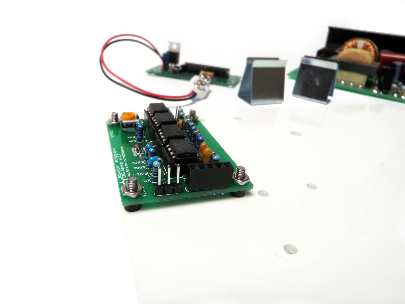
Step 4: Project Board


Build the Arduino project board as seen here (minus the 9V battery clip). Alternately, you can check out the Hackduino project for something similar.
Wire two 9V battery clips in series to create a +/-9V power supply.
Looking at the wires from the battery clips, connect the single red wire to the +V input on the Arduino project board. Next, connect the red and black wire junction to the ground input on the Arduino project board.
Solder a 6" green wire to one of the outer pins of the female socket. Solder a 6" black wire to the pin next to the green wire, and a 6" wire to the pin next to the black wire.
Solder the other end of the socket's green wire in line with the single black wire of the 9V socket supply. Solder the black wire in line with the center point of the two 9V sockets. Lastly, solder the red wire in line with the singular red wire (that is also connected to the voltage input on the project board)
Connect 6" green wires to pins D9 and A1. Also, connect two extra 6" black wires to ground.
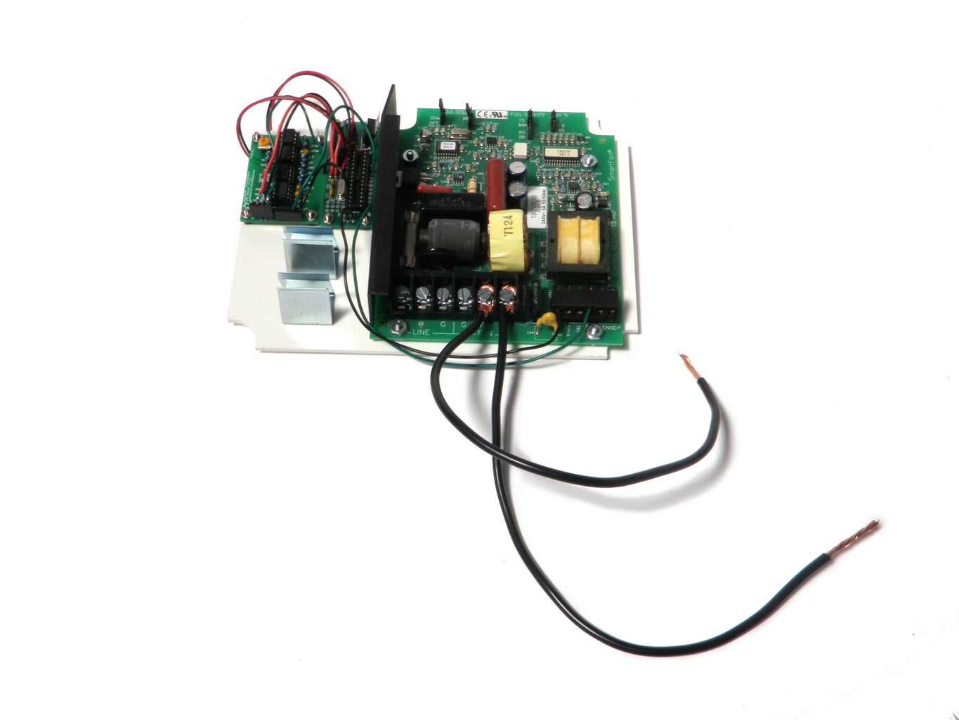
Step 5: Mount


Using nuts and bolts of appropriate size, mount the fan controller, Arduino project board, EMG board, and two 9V battery clips to the acrylic mounting base.
Step 6: Drill


Drill a 1/8" hole in the center of one of the smaller sides of the 8" x 6" x 3" project enclosure (the 6" x 3" side). Repeat this on the other side.
Widen one of the holes to 3/8" and the other hole to 7/32"
Step 7: Wire the Project Board


If you have not done so already, plug the socket from the project board into the male power headers on the EMG board. Make certain that the green wire aligns with V-.
Next, plug the green wire from pin A1 into Vout socket and one of the black wires into the ground socket on the EMG board.
Finally, connect the green wire from pin D9 into the 5V socket on the fan controller, and the black wire into the common socket.
Step 8: Wires


Cut two 14AWG wires that are around 8" long. Respectively, connect each of these wires to FW and FB on the fan controller board.
Step 9: Insert

Insert the acrylic base into your project enclosure such that the Arduino is closer to the side with the 3/8" hole.
Step 10: Solder and Mount


Solder a different colored solid core wire to each of the 1/4" stereo jack terminals. Mount the jack into the case.
Plug the wires into the EMG socket. It is good practice to plug the ground terminal from the jack into the reference socket.
Write down which color wire is associated with which connection. This will be important later.
Step 11: Power Cord


Pass a foot or so of the lamp cord through the 7/32" hole and tie a knot.
Connect one of the cords wire to the W-terminal and the other to the B-terminal on the fan controller.
Step 12: Put It All Together


Connect the wire from FW on the fan controller board to the side of the panel's sockets with the long slot.
Conned the wire from FB on the fan controller board to the side of the panel's sockets with the shorter slot.
Step 13: Program

Step 14: Transfer


After your Arduino is programmed, unplug it and transfer the ATMEGA chip from the Arduino to the project board inside the case.
Step 15: Power


Plug in your two 9V batteries and insert them into the enclosure.
Step 16: Case Closed


Place the panel atop the enclosure and fasten it into place with the enclosure's mounting screws.
Step 17: Drill


Drill through the center of one of the smaller sides of the 3" x 2" x 1" enclosure with an 1/8" drill bit (the 1" x 2" side). Repeat on the other side.
Widen one of the holes to 3/8". Widen the other hole to 1/2".
Step 18: Insert Wires


Pass the three electrode wires through the cable gland.
Mount the entire assembly inside the smaller project enclosure with the cable gland's mounting nut.
Step 19: Terminal Strip

Fasten each of the electrode plugs into one of the terminal strip's sockets. Fasten them firmly in place with the terminal strip's set nuts.
Step 20: Jack


Wire a second stereo jack with identical wiring to the one wired up earlier.
Connect the wire that corresponds with the reference socket to the black electrode wire.
Connect the wire that corresponds with the mid muscle socket to the red electrode wire.
Connect the wire that corresponds with the end muscle socket to the white electrode wire.
Step 21: Case Closed


Fasten shut the enclosure with its mounting screws.
Step 22: Connect

Connect the two enclosures together with a 1/4" male-to-male stereo cable.
Step 23: Plug

Plug in your lighting accessories and then plug the whole darned thing into the wall.
Step 24: Electrodes


To use it, you need to attach some electrodes to your face. Place one under your eye, one to the side of your eye, and one directly behind the ear.
Connect the red cable to the one under the eye, the white cable to the one next to the eye and the black cable to the one behind the ear.
Caution!!! Connecting your face to a DIY device that is plugged directly into the wall is a terrible idea. This Instructable was for entertainment purposes only. You should never replicate this.

Participated in the
Arduino Challenge

Participated in the
Make It Real Challenge


